A combined vehicle and train braking system and method

A combined braking, car-train technology, applied in electric braking systems, brakes, electric vehicles, etc., can solve the problem of limited retarder size and braking torque, limited wheel space, and the influence of trailer braking stability, etc. to improve the braking stability and reduce the braking load

Inactive Publication Date: 2016-08-24
郑州宇通集团有限公司
View PDF10 Cites 0 Cited by
  • Summary
  • Abstract
  • Description
  • Claims
  • Application Information

AI Technical Summary

Problems solved by technology

[0005] At present, only non-driven load-bearing bridges are used on semi-trailers or trailers, which do not have power transmission capabilities, and only play the role of carrying the car body and generating frictional braking force when necessary. Therefore, the retarder cannot be directly installed on semi-trailers or trailers. On the bridge, the original axle needs to be improved
[0006] The Chinese patent application number is 200510101686.4, and the name is an auxiliary braking device for semi-trailers and trailers. drive axle, but this device mainly describes the structure of the eddy current retarder and the installation method on the girder, and does not introduce the structure of the trailer drive axle, nor does it propose to form a joint brake with the air brake system to meet different working conditions car brake demand
[0007] Chinese patent application number 201210233128.3 discloses a trailer axle with a retarder, the retarder braking force only acts on a single axle, and the trailer axle of the actual heavy-duty vehicle train basically adopts the form of multiple bridges , the braking torque of the retarder cannot be evenly distributed on each axle of the trailer, which affects the braking stability of the trailer
[0008] Chinese patent application number 201310240519.2 discloses a trailer wheel retarder and its control method, but limited by the wheel space, the size and braking torque of the retarder are limited, it is difficult to fully Meet the braking requirements of heavy-duty trains with heavy loads

Method used


Image

  • A combined vehicle and train braking system and method
  • A combined vehicle and train braking system and method
  • A combined vehicle and train braking system and method

Examples


Embodiment Construction

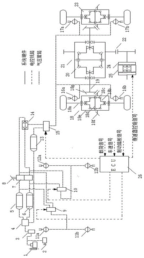
[0024] Such as figure 1 The vehicle-train combined braking system of the present invention is composed of an air pressure braking system, a retarder system and an electronic control unit ECU.

[0025] The pneumatic brake system is the service brake, installed on the tractor, including air compressor 1 and auxiliary air source 2, air compressor 1 and auxiliary air source 2 are connected in parallel, and after parallel connection, it is connected to the input port of pressure regulating valve 3, and the pressure regulating valve The output port of 3 is connected to the input port of the three-circuit distribution valve 4, and the output port of the three-circuit distribution valve 4 is respectively connected to the input ports of the air storage tank 5 in front of the tractor, the rear air storage tank 6 of the tractor and the air storage tank 13 of the trailer. The output port of the front air storage tank 5 of the tractor is respectively connected with the input port of the up...


PUM


Abstract

The invention discloses a united brake system and a united brake method for a combination vehicle. The united brake system is composed of an air pressure braking system, a retarder system and an electronic control unit (ECU); the retarder system is installed on a trailer by improving an axle of the trailer, so that brake torque of a retarder is evenly distributed to a front axle and a rear axle of the trailer through a trailer transmission system, and brake stability is improved; when the combination vehicle travels normally, an air compressor and an auxiliary air source inject high-pressure air into a front air storage tank of a motor tractor, a rear air storage tank of the motor tractor and an air storage tank of the trailer through a pressure adjusting valve and a three-loop protective valve; power distribution can be controlled accurately through electric control, under the condition of ensuring the brake requirement of the combination vehicle, the retarder system is used as much as possible, brake loads of a main brake are reduced, a double-control brake valve is adopted, under the condition that the electronic control part fails, the air control part works normally, and therefore the normal brake requirement is not affected.

Description

technical field [0001] The invention relates to a combined braking system for automobiles and trains, in particular to a combined braking system applied to an air pressure braking system for automobiles and trains and a retarder system for trailers, and belongs to the technical field of vehicle braking. Background technique [0002] Car trains are kinematic coupling bodies composed of tractors and trailers. Because they can realize the functions of "section transportation" and "drop and pull transportation", they have become an important means to improve transportation efficiency, but braking safety has always been a major hidden danger for car trains. , because the load of the car train is usually large, in the continuous braking (such as down a long slope) working condition, its service brake will form a thermal fading phenomenon due to long-term high-load work, resulting in a sharp drop in braking force. Therefore, many manufacturers now choose to install auxiliary brakin...

Claims


Application Information

Patent Timeline
Patent Type & Authority Patents(China)
IPC IPC(8): B60T13/66B60L7/24
Inventor 何仁许航
Owner 郑州宇通集团有限公司
Why Eureka
Try Eureka