Downhole remote control locking device and remote control locking method
What is AI technical title?
AI technical title is built by Patsnap AI team. It summarizes the technical point description of the patent document.
A technology of remote control lock and lock body, which is applied in the field of oil and natural gas drilling, and can solve the problems of pin discontinuity, easy failure, and small contact area of radial piston locking mechanism, etc.
Active Publication Date: 2016-12-28
BC P INC CHINA NAT PETROLEUM CORP +1
View PDF8 Cites 0 Cited by
Summary
Abstract
Description
Claims
Application Information
AI Technical Summary
This helps you quickly interpret patents by identifying the three key elements:
Problems solved by technology
Method used
Benefits of technology
Problems solved by technology
At present, the locking mechanisms used in most tools have the following deficiencies: some mechanisms cannot operate the locking and releasing of the locking mechanism in the tool through ground remote control, which is not conducive to the control of the tool; some mechanisms fix the two parts through pins , when separation is required, increase the pressure difference by throwing a ball and shear the pin to achieve separation. This mechanism can only be used to release the locking mechanism once and cannot be reused. It is not suitable for tools that need to be controlled multiple times in the well. The downhole working conditions are complicated, and sometimes unexpected impact may cause the pin to be interrupted, and the parts are released in advance, resulting in adverse consequences; The axial dimension of the mechanism is relatively long, and it will be disengaged and released when it bears a relatively large axial thrust. The radial piston locking mechanism has the disadvantages of small contact area, large stress, and easy failure. Moreover, the two mechanisms It is required to first determine the relative axial position of the two parts, and then trigger the locking sleeve or the radial piston action to lock, the operation is more cumbersome
Method used
Image
Click on the blue label to locate the original text in one second.
Reading with bidirectional positioning of images and text.
Examples
Embodiment 1
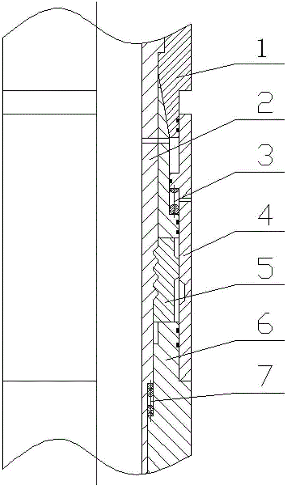
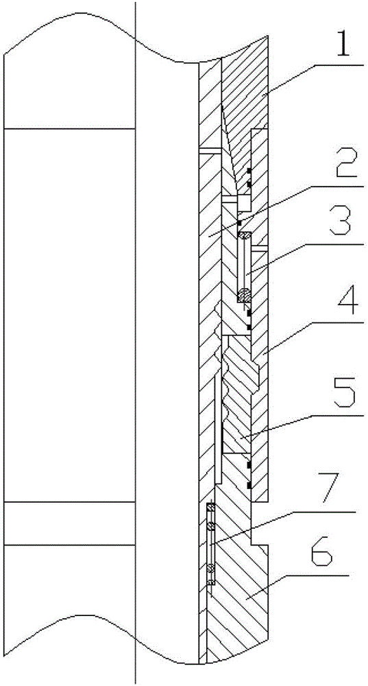
[0016] Embodiment 1: as figure 1 , figure 2 as shown,
[0017] The downhole remote control locking device consists of an upper housing 1, a locked body 2, an unlocking sleeve spring 3, an unlocking sleeve 4, a lock block 5, a body 6, and a locked body spring 7. There are bypass holes on the main body 6, the locked body 2 and the unlocking sleeve 4. The locked body 2 is installed on the inner side of the main body 6, the unlocking sleeve 4 is installed on the outer side of the main body 6, and the main body 6 and the upper casing 1 are connected with threads. The middle part of the body 6 is slotted, and the lock block 5 is installed in the groove of the body 6, and there are at least two slots between the lock block 5 and the body 6 in the circumferential direction. There is a groove in the middle of the locked body 2, and the tooth shape of the axial section meshes with the lock block 5. If the number of axial teeth is large, the axial thrust distributed on each tooth is ...
Embodiment 2
[0021] Embodiment 2: as figure 1 , figure 2 as shown,
[0022] Place the locked body spring and the unlocking sleeve spring on the middle part of the body and the lower step surface respectively, install the lock block in the through hole of the body, install the unlocking sleeve outside the body, connect the upper shell and the body with threads, and finally Put the locked body into the body from top to bottom.
[0023] During normal drilling, the mechanism is in the release state. When locking is required, increase the working displacement to the control displacement. The locked body is aligned with the bypass hole of the body, and the unlocking sleeve moves downward under the action of the pressure difference between the inner and outer rings. , the lock block is engaged with the annular groove of the locked body. At this time, it returns to the normal working displacement, and the mechanism is still in the locked state.
[0024] When release is required, the pump is s...
PUM
Abstract
A downhole remote control locking device and a remote control locking method belong to the technical field of oil and natural gas drilling. There are bypass holes on the main body, the locked body and the unlocking sleeve; the locked body is installed on the inner side of the main body, the unlocking sleeve is installed on the outer side of the main body, and the main body and the upper shell are connected by threads; the middle part of the main body is slotted, and the locking block is installed In the groove of the body, there are at least two slots between the lock block and the body in the circumferential direction; there is a groove in the middle of the locked body, and the tooth shape in the axial section meshes with the lock block; there is an annular groove on the inner side of the lower part of the unlocking sleeve. Groove, matched with the slope boss of the lock block; the unlocking sleeve spring is placed in the annular space between the unlocking sleeve and the upper end surface of the mid-diameter part of the body, and the locked body spring is placed between the lower part of the locked body and the large-diameter end of the body In the annular space between the sides; there is a sealing ring at the corresponding position of the unlocking sleeve and the body. The invention enables multiple locking and releasing of components.
Description
technical field [0001] The invention relates to an underground remote control locking device and a remote control locking method. It belongs to the technical field of oil and natural gas drilling. Background technique [0002] In the design of downhole tools for oil drilling, many situations involve the locking and releasing functions of a certain part of the tool. At present, the locking mechanisms used in most tools have the following deficiencies: some mechanisms cannot operate the locking and releasing of the locking mechanism in the tool through ground remote control, which is not conducive to the control of the tool; some mechanisms fix the two parts through pins , when separation is required, increase the pressure difference by throwing a ball and shear the pin to achieve separation. This mechanism can only be used to release the locking mechanism once and cannot be reused. It is not suitable for tools that need to be controlled multiple times in the well. The downh...
Claims
Application Information
Patent Timeline
Application Date:The date an application was filed.
Publication Date:The date a patent or application was officially published.
First Publication Date:The earliest publication date of a patent with the same application number.
Issue Date:Publication date of the patent grant document.
PCT Entry Date:The Entry date of PCT National Phase.
Estimated Expiry Date:The statutory expiry date of a patent right according to the Patent Law, and it is the longest term of protection that the patent right can achieve without the termination of the patent right due to other reasons(Term extension factor has been taken into account ).
Invalid Date:Actual expiry date is based on effective date or publication date of legal transaction data of invalid patent.

