Touch Sensor Device, Display Device And Electronic Equipment

A touch sensor and display device technology, applied in the direction of instruments, electrical digital data processing, optics, etc., can solve the problems of touch detection area touch drive time and touch detection period lengthening, display period and touch detection period convergence, etc., to achieve shortening Effects of touch drive time, shortened touch detection period, and improved sensitivity

Inactive Publication Date: 2014-09-17
JAPAN DISPLAY INC
View PDF8 Cites 13 Cited by
  • Summary
  • Abstract
  • Description
  • Claims
  • Application Information

AI Technical Summary

Problems solved by technology

Therefore, it is difficult to make the display period and the touch detection period converge within the limited frame period.
[0021] As described above, in the touch sensor device of the comparative example and the display device with a touch sensor, there is the following problem: the inefficiency due to the time corresponding to the excess performance of the pulse of the touch drive signal is not related to the number of electrodes of the touch drive electrodes or the number of scans. Correspondingly, the touch driving time of the touch detection area and the touch detection period become longer

Method used


Image

  • Touch Sensor Device, Display Device And Electronic Equipment
  • Touch Sensor Device, Display Device And Electronic Equipment
  • Touch Sensor Device, Display Device And Electronic Equipment

Examples


specific Embodiment approach

[0130] Hereinafter, embodiments of the present invention will be described in detail based on the drawings. In addition, in all the drawings for explaining the embodiment, in principle, the same reference numerals are assigned to the same parts, and their repeated descriptions are omitted. In addition, cross-sectional hatching is appropriately omitted for easy understanding. In the description, as the direction of the surface constituting the touch detection area in the device, etc., the in-plane horizontal direction is referred to as the X direction, and the in-plane vertical direction is referred to as the Y direction. The vertical direction of the surface of the touch detection area or the like, or the thickness direction of the touch sensor device or the like is defined as the Z direction.

[0131]

[0132] A touch sensor device and a display device with a touch sensor function according to the present embodiment will be described below. The outline of the touch sensor...

Embodiment approach 1

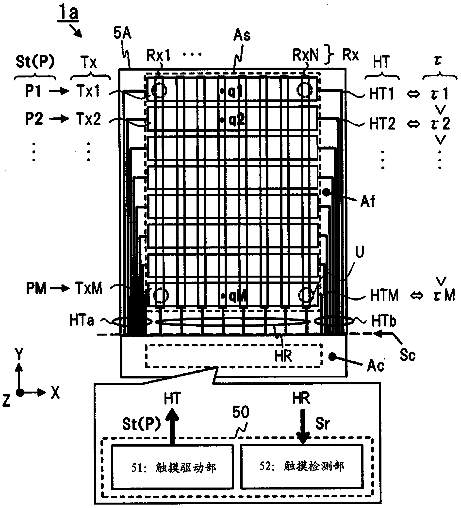
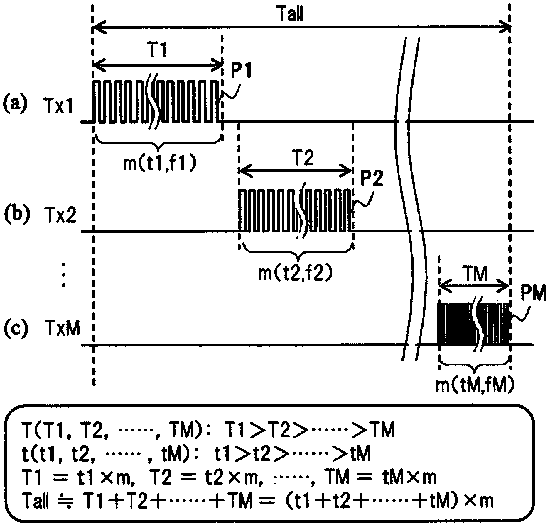
[0183] Based on the above comparative example, using Figure 1 to Figure 9 , the touch sensor device 1a as Embodiment 1A of the present invention will be described. In Embodiment 1A, a configuration is shown in which a plurality of touch drive electrodes Tx in the touch detection area As with different lengths of the lines HT are lead-out wirings to the touch drive electrodes Tx as the touch drive signal St from the circuit of the touch drive unit. Each of the plurality of pulses P of M types, pulses P1 to pulse PM, whose time is adjusted to an optimum time in accordance with the time constant of the wiring HT is generated and applied to the touch drive electrode Tx.

[0184] [(1) Panel part plane]

[0185] figure 1 This is an example of the configuration of the XY plane including electrodes, wiring, and a circuit portion as an outline of the touch sensor device 1a according to Embodiment 1A. The panel portion 5A of the touch sensor device 1a has a touch detection area As, ...

Embodiment approach 1

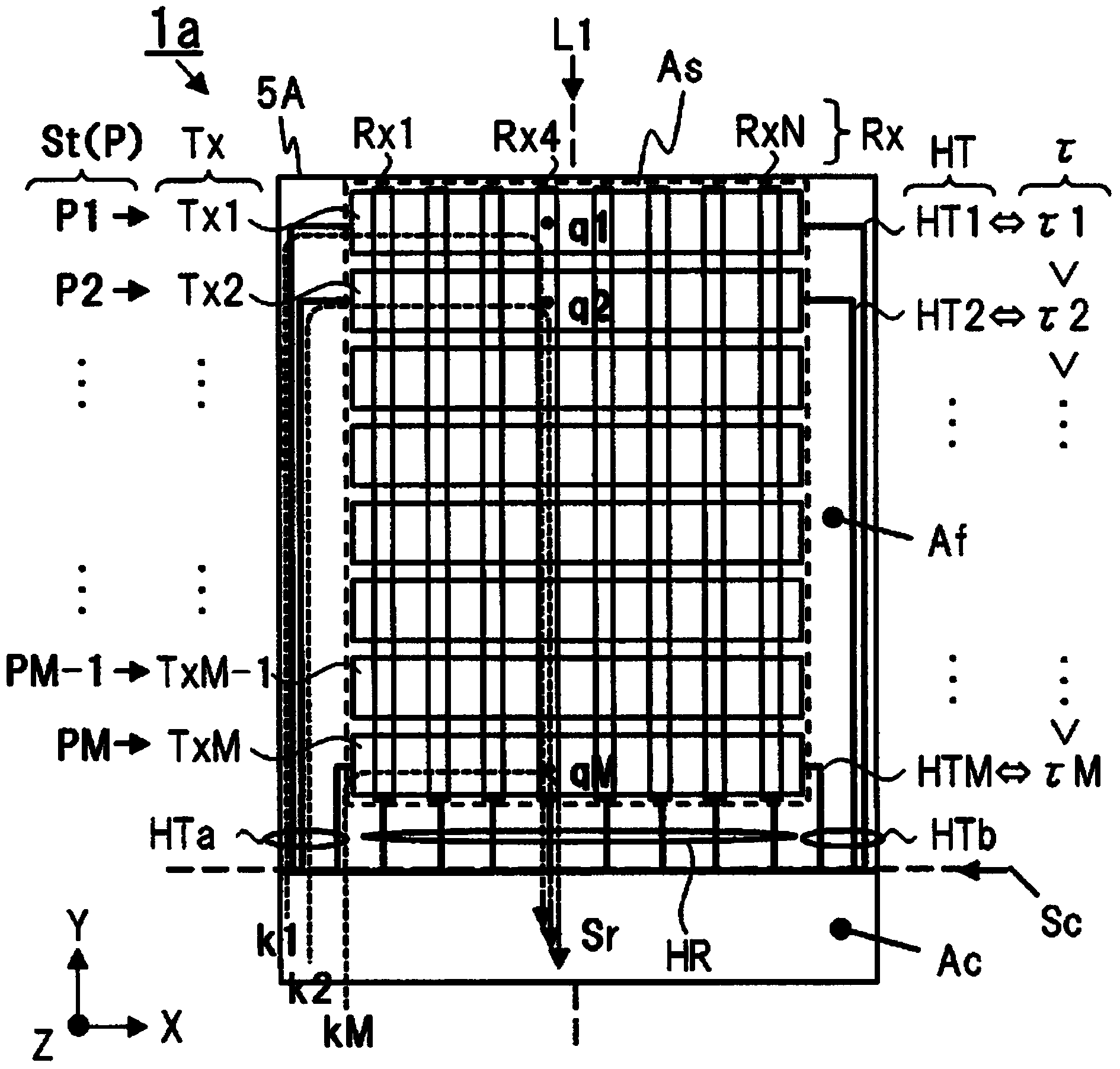
[0242] Figure 10 The structure of the XY plane of the touch sensor device 1b of Embodiment 1B is shown. In Embodiment 1B, as the various types of pulses P generated from the touch drive unit 51 , pulses P of a type less than the number of electrodes and the number of scans M as the touch drive electrodes Tx described above are generated, and the touch Each group of touch drive electrodes Tx within the detection area As is applied. A group of touch drive electrodes Tx composed of one or more touch drive electrodes Tx is represented by TxG.

[0243] exist Figure 10 example, as the kind of pulse P, as stated in the Figure 4 Thus, there are three kinds of pulses P having a time t such as tA>tB>tC, namely pulse PA, pulse PB, and pulse PC. In contrast, the plurality of touch drive electrodes Tx in the touch detection area As are divided into three groups, namely group TxGA, group TxGB, and group TxGC. For example, the group TxGA on the upper side in the Y direction includes ...


PUM


Abstract

In relation to touch sensors, technique capable of shortening total touch drive time and a touch detection period or suppressing increase thereof are provided. In a panel unit (5A) of a touch-sensor device (1a), a touch drive unit (51) generates a first pulse to an M-th (P) pulses which are pulses of a plurality of types having mutually different cycles in accordance with differences in time constants with respect to paths including wirings (HR) of a peripheral area (Af), touch drive electrodes (Tx), units of touch detection (U), touch detection electrodes (Rx), and wirings of the peripheral area through which pulses of touch drive signals (St) to the plurality of touch drive electrodes (Tx) are transmitted in a touch detection area (As) in which the plurality of units of touch detection (U) formed by pairs of the plurality of touch drive electrodes (Tx) and the plurality of touch detection electrodes (Rx) are formed like a matrix, and the touch drive unit applies the pulses.

Description

technical field [0001] The present invention relates to technologies such as a touch sensor device (also called a touch panel), a display device with a touch sensor function, and electronic equipment. Background technique [0002] Touch sensor devices are mounted as input components in various electronic devices such as smartphones and display devices. Examples of touch sensor devices include a touch sensor device dedicated to the touch sensor function, an external or cover-integrated display device with a touch sensor, and a display device with a touch sensor in which electrodes constituting a touch sensor device are built into a display panel. Wait. In addition, an external-type or cover-integrated display device with a touch sensor is also called an on-cell type display device with a touch sensor. A display device with a touch sensor in which electrodes of a touch sensor are built into a display panel is also referred to as an in-cell type display device with a touch se...

Claims


Application Information

Patent Timeline
Patent Type & Authority Applications(China)
IPC IPC(8): G06F3/041G06F3/044G02F1/1333
CPCG02F1/13338G06F2203/04104G06F3/044G06F3/04164G06F3/04166G06F3/0445G06F3/0446G06F3/0412G06F3/0418G06F2203/04108
Inventor 铃木崇章安住康平
Owner JAPAN DISPLAY INC
Why Eureka
Try Eureka