Batteries with thermal trigger elements

A battery, thermal trigger technology, applied in the direction of batteries, electrical components, secondary batteries, etc., can solve the problems of battery safety hazards, battery damage, etc.

Active Publication Date: 2017-06-23
ROBERT BOSCH GMBH +1
View PDF3 Cites 0 Cited by
  • Summary
  • Abstract
  • Description
  • Claims
  • Application Information

AI Technical Summary

Problems solved by technology

For example, charging the battery above the specified voltage limit and discharging the battery below the specified voltage limit can lead to the destruction of the battery
[0003] Furthermore, especially in electric vehicles, overloading or overheating of the battery during operation is a danger to the safety of the battery as well as the load

Method used


Image

  • Batteries with thermal trigger elements

Examples


Embodiment Construction

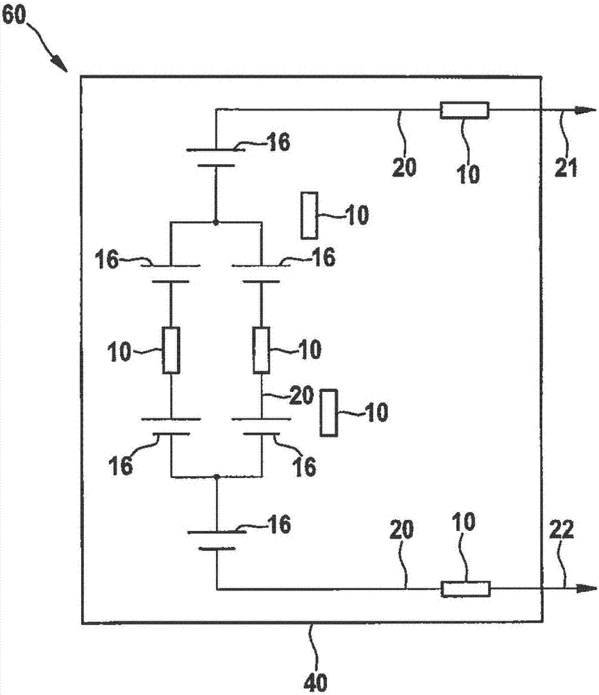
[0022] exist figure 1 An exemplary embodiment of a schematically represented battery 60 according to the invention is shown in FIG. The battery 60 includes a battery case 40, which is figure 1 Only schematically depicted in , as well as the two terminals 21 and 22, via which the battery 60 can be electrically conductively connected to the load or to the high-voltage grid, more precisely to the main protective device of the high-voltage grid. A battery pack 20 is arranged inside the battery housing 40 , which connects the two terminals 21 , 22 to each other and which has a plurality of battery cells 16 in the exemplary embodiment, some of which are connected in series to the battery pack 20 and Others are connected in parallel to the battery pack 20 and the further battery cells 16 . The battery pack 20 is also an electrical connection between the connections 21 and 22 , which in the exemplary embodiment has a plurality of battery cells 16 connected in series or in parallel t...


PUM


Abstract

The invention provides a battery (60), which comprises a battery housing (40) and two connections (21, 22), via which the battery (60) can be electrically conductively connected to a load. Furthermore, the accumulator (60) comprises an accumulator pack (20) arranged in an accumulator housing (40), which connects two terminals (21, 22) to one another and has at least one connected in series and / or in parallel to The battery cells (16) of the battery pack (20). The accumulator ( 60 ) according to the invention has at least one thermal activation element ( 10 ) arranged in the accumulator housing ( 40 ), which is provided for the presence of a predetermined first temperature is triggered and thus indicates the presence of this predetermined first temperature in the region of the thermal activation element (10).

Description

technical field [0001] The invention relates to an accumulator with an accumulator housing having at least one thermal activation element arranged in the accumulator housing, the thermal activation element being provided for when a predetermined first temperature is present in the region of the thermal activation element is triggered and thus indicates the presence of a predetermined first temperature in the region of the thermal activation element. Background technique [0002] In electrically driven vehicles, batteries or accumulators are used as energy source. Such accumulators are currently often assembled from a number of lithium-ion accumulator cells, since in the current state of the art this combination has the greatest energy density at the lowest weight, for example compared to nickel-based or lead-based accumulators. Furthermore, due to this high energy content, certain safety standards must be met both during production and during use of such accumulators. Fail...

Claims


Application Information

Patent Timeline
Patent Type & Authority Patents(China)
IPC IPC(8): H01M10/48H01M10/42H02H7/18H02H5/04B60L11/18
CPCB60L50/64B60L58/21B60L58/24B60L3/0046B60L3/04B60L2240/545H01M10/488H01M10/486H01M10/482H01M10/0525H01M2200/10H01M2220/20Y02E60/10Y02T10/70H01M50/581H01M10/425
Inventor S·贝格曼G·加兰布S·齐格勒
Owner ROBERT BOSCH GMBH
Why Eureka
Try Eureka