Rotary pot holder

A technology of rotating pots and ring columns, applied in the direction of the cooker's support, etc., can solve the problems of uneven spreading, troublesome work, and no solution, etc., and achieve the effect of uniform heating

Inactive Publication Date: 2016-06-15
张慧洁
View PDF6 Cites 0 Cited by
  • Summary
  • Abstract
  • Description
  • Claims
  • Application Information

AI Technical Summary

Problems solved by technology

In fact, in the process of cooking, a very basic operation is to heat the food in the pot evenly one by one. For this reason, it is necessary to constantly turn the food with a spatula. This is a troublesome job, but it is not convenient. Solution; In addition, when using cooking pot pancakes, it is necessary to use a spatula to flatten the noodles or egg cakes. This work is also troublesome, and it is also uneven. for ease and convenience

Method used


Image

  • Rotary pot holder
  • Rotary pot holder
  • Rotary pot holder

Examples


Embodiment 1

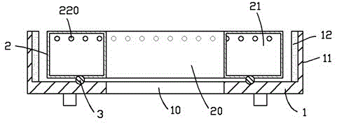
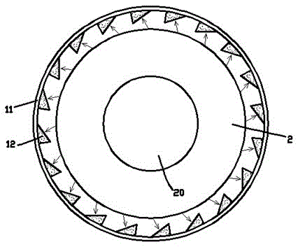
[0013] exist figure 1 , figure 2 In the first embodiment shown, the rotary pot seat includes a base 1, the base 1 is in the shape of a barrel with an opening facing upwards; the bottom surface of the base 1 is provided with a flame hole 10 for allowing the lower flame to escape into the base; the base 1 An annular column 2 is surrounded inside; the interior of the annular column 2 is an annular cavity 21 that can be injected into water; the upper peripheral wall of the annular cavity 21 is provided with a circle of air holes 220, and each air hole 220 is along the side of the outer peripheral wall. to the air outlet, and the angle between the air outlet direction of each air hole 220 and the radial direction of the air hole is equal, that is, when each air hole 220 is ejected at the same air outlet speed, the gas ejected in each air hole will generate a large impact on the annular cavity 21. Equal torque; the side wall 11 surrounding the annular column 2 on the base 1 has re...

Embodiment 2

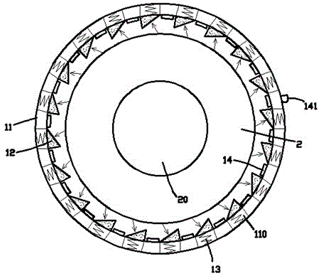
[0016] image 3 Shown is the second embodiment of the rotary pot seat, which is different from the first embodiment in that: the recoil slopes 12 on the side wall 11 of the base 1 are movable components, and pass through the side wall 11 The spring 13 in the concave hole 110 is ejected from the concave hole; a section of arc-shaped sliding piece 14 is respectively arranged between each of the recoil slopes 12, and each of the arc-shaped sliding pieces 14 is fixed to each other to form a broken A continuous ring, a driving rod 141 leading to the outside of the side wall of the base 1 is fixed on the intermittent ring; when the driving rod 141 is moved along the side wall 11 of the base 1, the Each of the arc-shaped sliding pieces 14 on the intermittent ring presses against each of the recoil slopes 12 , and presses each of the recoil slopes 12 into the interior of the concave hole 110 .

[0017] The outstanding advantage of the second embodiment is that: when the pot body does...


PUM


Abstract

The invention provides a rotating pot base, comprising a base, the base is in the shape of a barrel with an opening facing upwards; the bottom surface of the base is provided with a flame hole for allowing the lower flame to enter the base; the base surrounds an annular column; the base The inside of the annular column is an annular cavity that can be injected into water; a circle of air holes is opened on the upper peripheral wall of the annular cavity, and each air hole exits along the side of the outer peripheral wall, and the air outlet direction of each air hole is consistent with the radius of the air hole. The intersection angles of the directions are equal; the side wall surrounding the annular column on the base has a recoil slope in a circumferential array; the recoil slope is perpendicular to the airflow direction impacting on the central position of the recoil slope; the The bottom of the ring column cooperates with the base through the ring slide rail mechanism, so that the ring column can freely rotate around its own central axis. The rotating pot seat can make the process of cooking and pancakes very easy and convenient, thereby improving people's daily life.

Description

technical field [0001] The invention relates to the field of cooking equipment, in particular to a pot support. Background technique [0002] Although the current cooking utensils are becoming more and more high-end and luxurious, and pay attention to quality, the structural technical improvement is progressing slowly. In fact, in the process of cooking, a very basic operation is to heat the food in the pot evenly one by one. For this reason, it is necessary to constantly turn the food with a spatula. This is a troublesome job, but it is not convenient. Solution; in addition, when using cooking pot pancakes, it is necessary to use a spatula to flatten the dough or egg cakes, which is troublesome and uneven. It is also necessary to propose a convenient solution to this problem to make it more For ease and convenience. Contents of the invention [0003] In view of the above problems, the object of the present invention is to provide a rotating pot base, which can make the ...

Claims


Application Information

Patent Timeline
Patent Type & Authority Patents(China)
IPC IPC(8): A47J36/34
Inventor 陈帅宏
Owner 张慧洁
Why Eureka
Try Eureka