Ventilation transverse locking type unit curtain wall system

A unit curtain wall and horizontal locking technology, applied in ventilation systems, space heating and ventilation, walls, etc., can solve problems such as high maintenance costs, damage to stressed structures, affecting ventilation and sealing of curtain walls, and achieve reasonable structural design and maintenance. Low cost and excellent sealing effect

Active Publication Date: 2014-09-24
李哲先
View PDF10 Cites 4 Cited by
  • Summary
  • Abstract
  • Description
  • Claims
  • Application Information

AI Technical Summary

Problems solved by technology

[0003] Ordinary curtain walls installed with ventilators, due to unreasonable design, cause a certain degree of damage to the stressed structure, which is easily deformed and damaged under the action of wind pressure, thereby affecting the ventilation and sealing (watertightness and airtightness) performance of the curtain wall. It reduces the use function and service life of the curtain wall; and affects the decorative effect of the curtain wall to a certain extent; if the glass plate needs to be replaced and maintained, the operation is complicated, resulting in high maintenance costs in the later period

Method used


Image

  • Ventilation transverse locking type unit curtain wall system
  • Ventilation transverse locking type unit curtain wall system
  • Ventilation transverse locking type unit curtain wall system

Examples


Embodiment 1

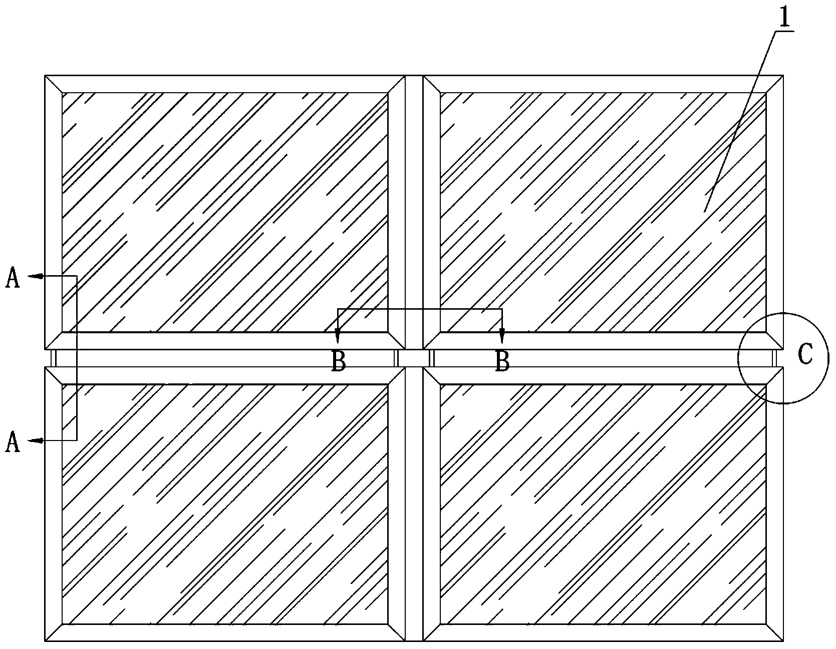
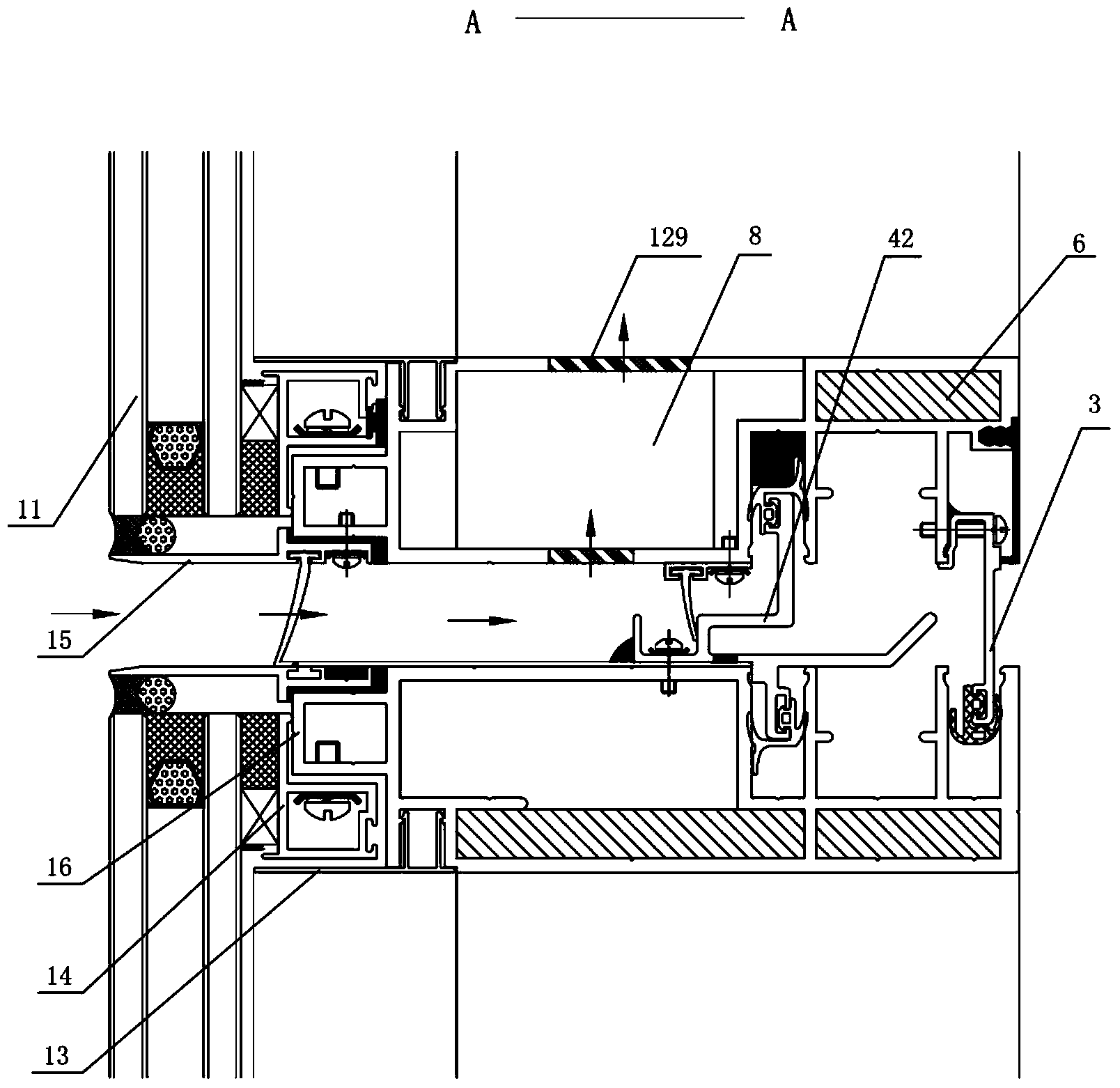
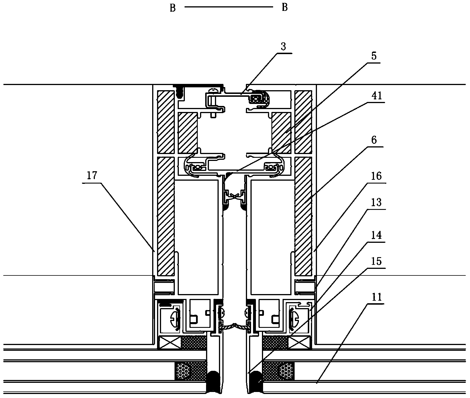
[0029] Such as Figure 1 to Figure 4 As shown, the preferred implementation of the ventilated cross-locking unit curtain wall system in this embodiment includes several mutually spliced ​​curtain wall units 1, and the two adjacent curtain wall units 1 in the horizontal direction pass through the air-tight connector 3 and the water-tight connector. 41 connection, and the two adjacent curtain wall units 1 in the vertical direction are fixed by the airtight connecting piece 3 , the sump 42 and the horizontal lock control piece 5 . A transition isobaric chamber 91 , an isobaric chamber 92 and a sealed chamber 93 are formed between the two adjacent curtain wall units. in, figure 1 Four curtain wall units 1 are shown in , of course, the ventilated cross-locking unit curtain wall system in other embodiments also includes more curtain wall units 1; figure 2 The direction of the arrow in indicates the direction of air flow.

[0030] Each curtain wall unit 1 includes glass panels 11...

Embodiment 2

[0038] Please refer to Figure 9 to Figure 11 As shown, the difference between the second embodiment and the first embodiment is that the decorative moldings 2 are installed on the curtain wall unit 1 and the structure of the second profile 17 in the curtain wall unit 1 is different.

[0039] The decorative line 2 is fixed to the second profile 17 through the connecting hanger 7, and the positioning plate 15 in the second profile 17 is replaced by the connecting hanger 7, that is, the connecting hanger 7 not only connects the decorative line 2 and the second profile 17 , while being fixed with the glass plate 11; meanwhile, the decorative lines 2 are also fixed with the glass plate 11.

[0040] The second profile 17 is provided with first to fifth cavities 170, 171, 172, 173, 174, first to sixth connecting grooves 175, 176, 177, 178, 179, 1707, the first cavity The outer wall of 171 is used to fix the glass sub-frame 14, the second cavity 172 and the third cavity 173 are used...


PUM


Abstract

The invention discloses a ventilation transverse locking type unit curtain wall system which comprises multiple curtain wall units spliced with each other. Two adjacent curtain wall units in the vertical direction are fixedly connected through a transverse locking control piece, an airtight seal connecting piece and a watertight seal connecting piece, and two adjacent curtain wall units in the horizontal direction are connected through an airtight seal connecting piece and a watertight seal connecting piece. According to the ventilation transverse locking type unit curtain wall system, ventilation can be achieved, and glass plates can be replaced or maintained conveniently.

Description

technical field [0001] The invention relates to a ventilated curtain wall, in particular to a ventilated horizontal lock type unit curtain wall system. Background technique [0002] Curtain wall, as the outer enclosure structure of high-end buildings, has become a symbol of modern buildings. In order to solve the ventilation of the building curtain wall, the existing building curtain wall generally all adopts a top-hanging opening window on the building curtain wall to solve the indoor and outdoor ventilation problem of the curtain wall. However, for high-rise buildings or super-tall buildings, if traditional opening windows are used to solve the ventilation of curtain walls, then the configuration requirements for opening window hardware are very high, and there are very large safety hazards, and relevant national regulations also have restrictions on this sex requirements. In order to ensure the indoor ambient air quality of such buildings, it has become a development tr...

Claims


Application Information

Patent Timeline
Patent Type & Authority Applications(China)
IPC IPC(8): E04B2/88F24F7/00
Inventor 李哲先
Owner 李哲先
Why Eureka
Try Eureka