
Modular nitrification and denitrification membrane bioreactor

A membrane bioreactor, nitrification and denitrification technology, used in biological treatment devices, sustainable biological treatment, chemical instruments and methods, etc., can solve the problems of downtime, high maintenance costs, and high energy consumption, and improve the reliability of water supply. , Long stable operation cycle, and the effect of expanding the scope of application

Pending Publication Date: 2016-11-16
南京瑞洁特膜分离科技有限公司
View PDF7 Cites 2 Cited by
  • Summary
  • Abstract
  • Description
  • Claims
  • Application Information

AI Technical Summary

Problems solved by technology

[0003] The traditional biological denitrification process usually adopts pre-denitrification or post-denitrification, so that the sewage can remove nitrogen through the anaerobic-anoxic-aerobic zone in the horizontal direction. In order to achieve a better denitrification effect, it is often necessary to set The backflow device returns the mixed liquid in the aerobic zone to the front end. On the one hand, this traditional process occupies a large area and requires high civil construction costs. On the other hand, a special lifting device is required, which not only consumes high energy consumption, but also requires high maintenance costs. At the same time, Once the traditional process fails, it often needs to be shut down for maintenance, and the quality of the effluent water cannot be guaranteed. These shortcomings limit the further application of flat membranes in water treatment, especially in large-scale projects.

Method used


Image

  • Modular nitrification and denitrification membrane bioreactor
  • Modular nitrification and denitrification membrane bioreactor
  • Modular nitrification and denitrification membrane bioreactor

Examples


Embodiment Construction

[0021] It should be noted that, in the case of no conflict, the embodiments of the present invention and the features in the embodiments can be combined with each other.

[0022] In describing the present invention, it should be understood that the terms "center", "longitudinal", "transverse", "upper", "lower", "front", "rear", "left", "right", The orientations or positional relationships indicated by "vertical", "horizontal", "top", "bottom", "inner", "outer", etc. are based on the orientation or positional relationships shown in the drawings, and are only for the convenience of describing the present invention Creation and simplification of description, rather than indicating or implying that the device or element referred to must have a specific orientation, be constructed and operate in a specific orientation, and therefore should not be construed as limiting the invention. In addition, the terms "first", "second", etc. are used for descriptive purposes only, and should no...


PUM


Abstract

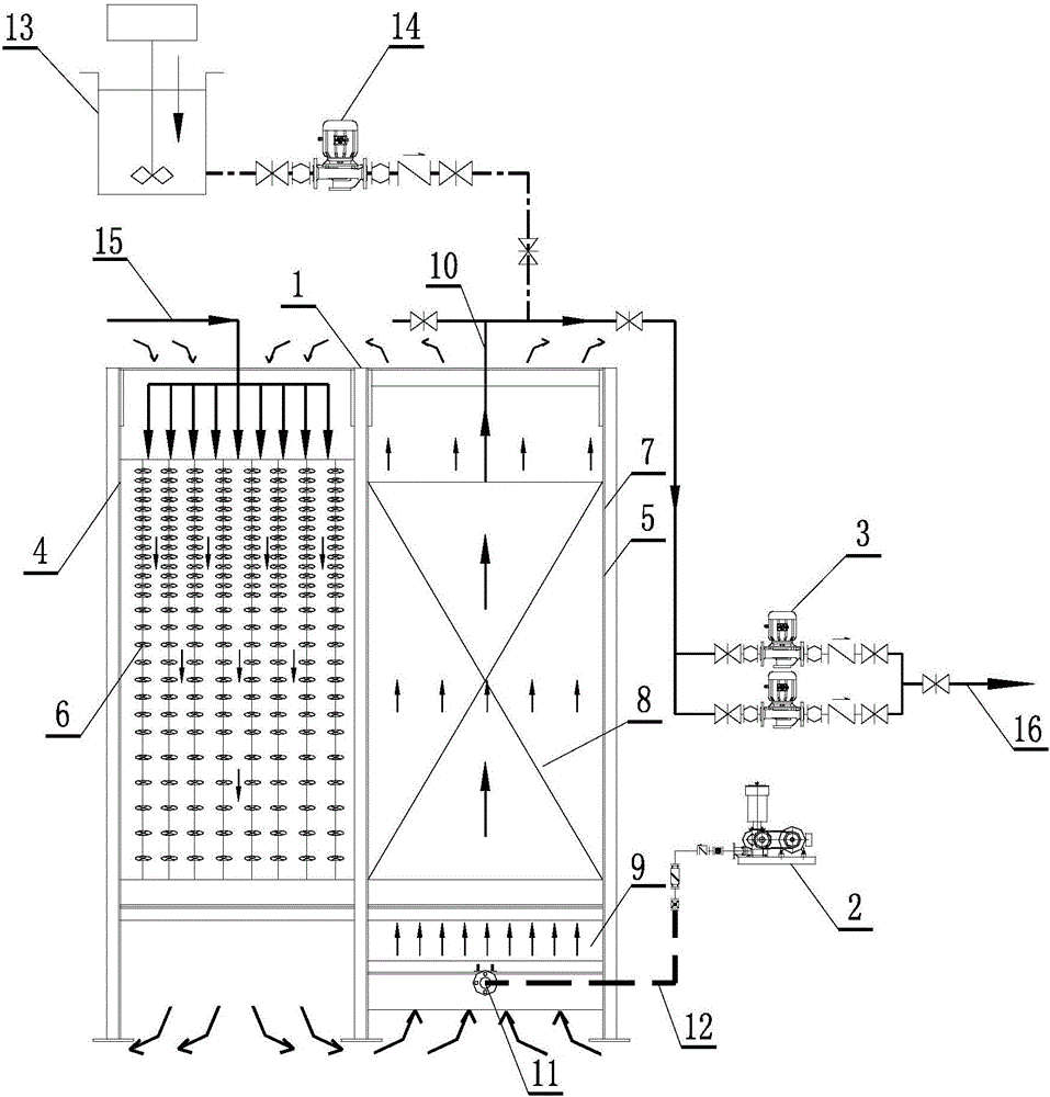
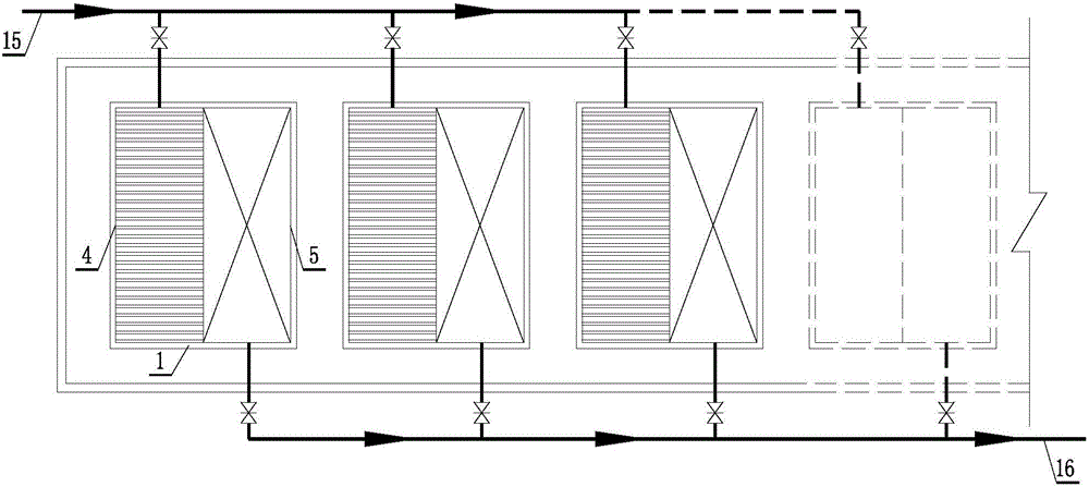
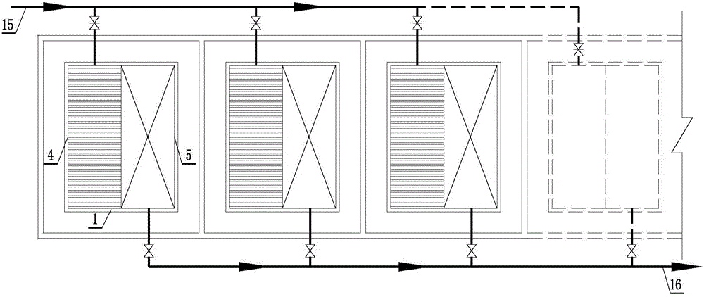
The invention discloses a modular nitrification and denitrification membrane bioreactor. The modular nitrification and denitrification membrane bioreactor comprises a module, wherein a nitrification and denitrification reaction area is arranged on the left side in the module, biological filler with the density reduced gradually is arranged in the vertical direction in the nitrification and denitrification reaction area, a membrane biological reaction area is arranged on the right side in the module, a membrane box is arranged in the membrane biological reaction area, membrane elements are arranged in the membrane box, an aeration box is arranged below the membrane box in the membrane biological reaction area, sewages flows from top to bottom in the nitrification and denitrification reaction area, and treated water is discharged through a self-priming pump. The nitrification and denitrification reaction area and the membrane biological reaction area are integrated to form a module, the modular nitrification and denitrification membrane bioreactor can adapt to various occasions through combination of modules, and requirements of various sewage treatment scales are met; each module is an independent treatment unit, the modules are not affected during overhaul, ceaseless water discharging all year round can be completely realized, the water supply reliability is greatly improved, the system is stable, the operation period is long, and the application range of MBR (membrane biological reactor) engineering is extended.

Description

technical field [0001] The invention belongs to the field of sewage treatment and relates to a modular nitrification and denitrification membrane bioreactor device. Background technique [0002] Membrane bioreactor, as an efficient and practical sewage treatment device, has been widely used in the treatment of municipal sewage and various organic industrial wastewater. It combines the advantages of traditional biological treatment technology and membrane separation technology, makes full use of the effective interception of microorganisms by ultrafiltration membrane, can effectively resist the impact caused by organic load and temperature difference, and ensures the long-term reliable and stable operation of the system. [0003] The traditional biological denitrification process usually adopts pre-denitrification or post-denitrification, so that the sewage can remove nitrogen through the anaerobic-anoxic-aerobic zone in the horizontal direction. In order to achieve a better ...

Claims


Application Information

Patent Timeline
Patent Type & Authority Applications(China)
IPC IPC(8): C02F3/02C02F3/30
CPCC02F3/1268C02F3/302C02F2203/006Y02W10/10
Inventor 周保昌李海霞张敏
Owner 南京瑞洁特膜分离科技有限公司
Learn More