
Improved shortest path bridging in a multi-area network

A multi-path and area technology, applied in the field of Ethernet networks, can solve the problems of network design that cannot be easily decoupled from each other, lack of specificity, and computational complexity

Active Publication Date: 2014-09-24
TELEFON AB LM ERICSSON (PUBL)
View PDF4 Cites 10 Cited by
  • Summary
  • Abstract
  • Description
  • Claims
  • Application Information

AI Technical Summary

Problems solved by technology

Also, computational complexity (which tends to scale exponentially with network size) benefits from splitting the network into smaller regions
However, current multi-area networks do not currently materialize the idea of ​​multipathing as used by 802.1aq, which is edge-based traffic distribution over multiple sets of equivalence trees
Therefore, network designs in different regions of the network cannot be easily decoupled from each other

Method used


Image

  • Improved shortest path bridging in a multi-area network
  • Improved shortest path bridging in a multi-area network
  • Improved shortest path bridging in a multi-area network

Examples


Embodiment Construction

[0024] In the following description, numerous specific details are set forth. However, it is understood that embodiments of the invention may be practiced without these specific details. In other instances, well-known circuits, structures and techniques have not been shown in detail in order not to obscure the description. However, it will be understood by those skilled in the art that the present invention may be practiced without such specific details. Those of ordinary skill in the art, using the included descriptions, will be able to implement appropriate functionality without undue experimentation.

[0025]The multi-area network structure described in this paper is , which simplifies the task of providing loop-free symmetric connectivity between nodes in different areas. For Ethernet, a loop in the forwarding path can be disastrous if the forwarding path is a multicast path. Therefore, the use of routing hierarchies is advantageous, as opposed to peer-to-peer mesh inte...


PUM


Abstract

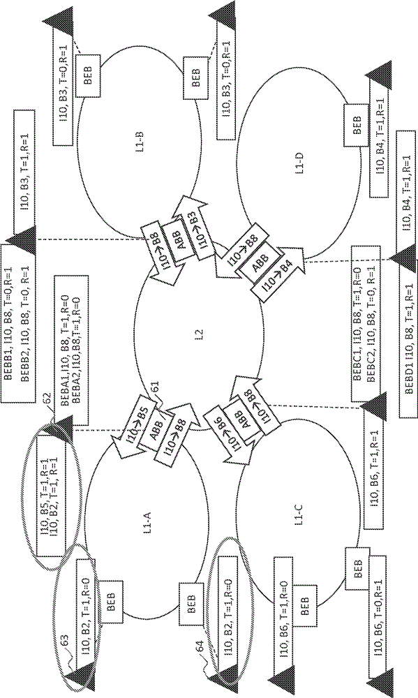
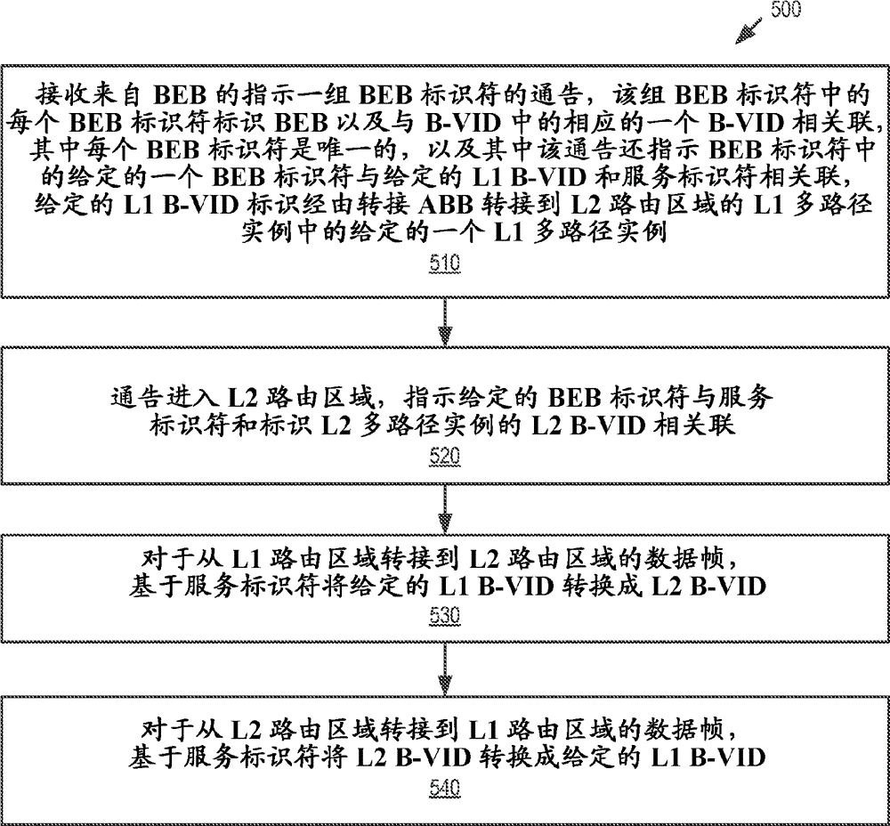
A method that improves multi-area routed Ethernet network design, in which multipath implementation in each of the areas is independent of each other area to allow optimal network design in each area. The network implements a shortest path bridging medium access control (SPBM) protocol. The areas include a Level 2 (L2) routing area coupled to a Level 1 (L1) routing area via multiple area border bridges (ABBs). The L1 routing area including a backbone edge bridge (BEB) coupled to the ABBs via multiple L1 multipath instances identified by respective backbone VLAN identifiers (B-VIDs). The ABBs receive an advertisement from the BEB that indicates a set of BEB identifiers, each of which identifies the BEB and is associated with a respective B-VID. Each of the BEB identifiers is unique. The ABBs also advertise into the L2 routing area, and translate the B-VIDs based on service identifiers for frames transiting the ABBs.

Description

[0001] Related Application Cross Reference [0002] This application claims priority to US Provisional Patent Application No. 61 / 592,388, filed January 30, 2012. technical field [0003] Embodiments of the present invention relate to the field of Ethernet networks; and more particularly, to improved shortest path bridging in multi-area networks. Background technique [0004] Ethernet was originally developed to provide network connectivity over a passive shared medium such as a local area network (LAN). Over time, Ethernet has evolved into an active switched network that provides bridging and discovery of the location of endpoints across bridged network segments. Where multiple bridges are used to interconnect network segments, there are often multiple potential paths to the same destination. The benefit of this multipath architecture is that it provides path redundancy between bridges and allows capacity to be added to the network in the form of additional links. In orde...

Claims


Application Information

Patent Timeline
Patent Type & Authority Applications(China)
IPC IPC(8): H04L12/46H04L12/751H04L45/02H04L45/16H04L45/18
CPCH04L45/66H04L12/462H04L12/4625H04L45/02H04L12/4641H04L45/16H04L45/18H04L45/026H04L45/03
Inventor D.I.艾伦J.法卡斯P.萨尔特西迪斯M.朱利恩
Owner TELEFON AB LM ERICSSON (PUBL)
Learn More