Combined rack

A combination and rack technology, applied in the field of racks, can solve problems such as difficult adjustment and assembly, and difficult assembly of combined racks

Inactive Publication Date: 2014-10-01
ULIKE
View PDF7 Cites 3 Cited by
  • Summary
  • Abstract
  • Description
  • Claims
  • Application Information

AI Technical Summary

Problems solved by technology

[0004] The invention relates to a combined storage rack and its sliding set, so as to solve the problems in the

Method used


Image

  • Combined rack
  • Combined rack
  • Combined rack

Examples


Example Embodiment

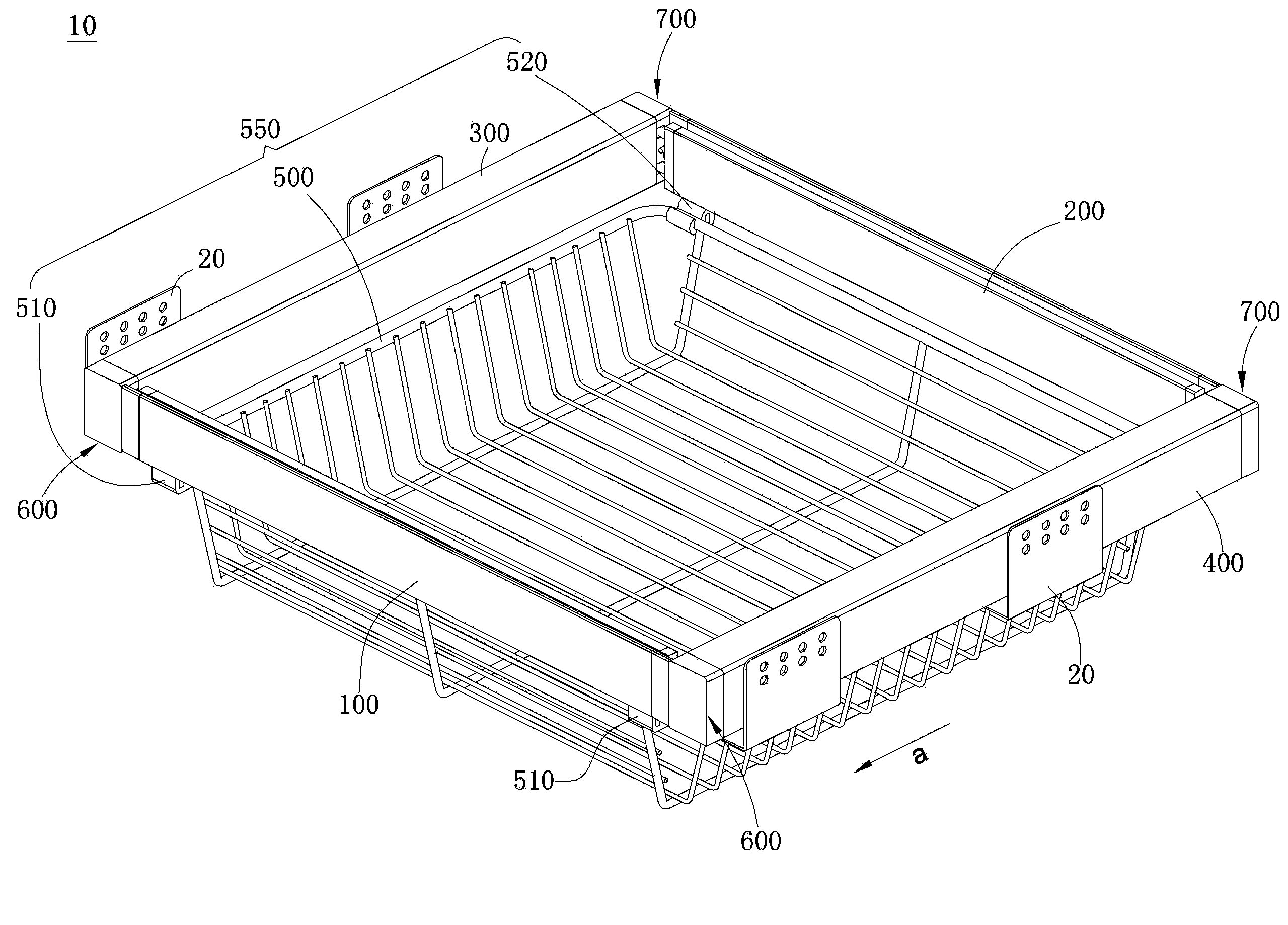
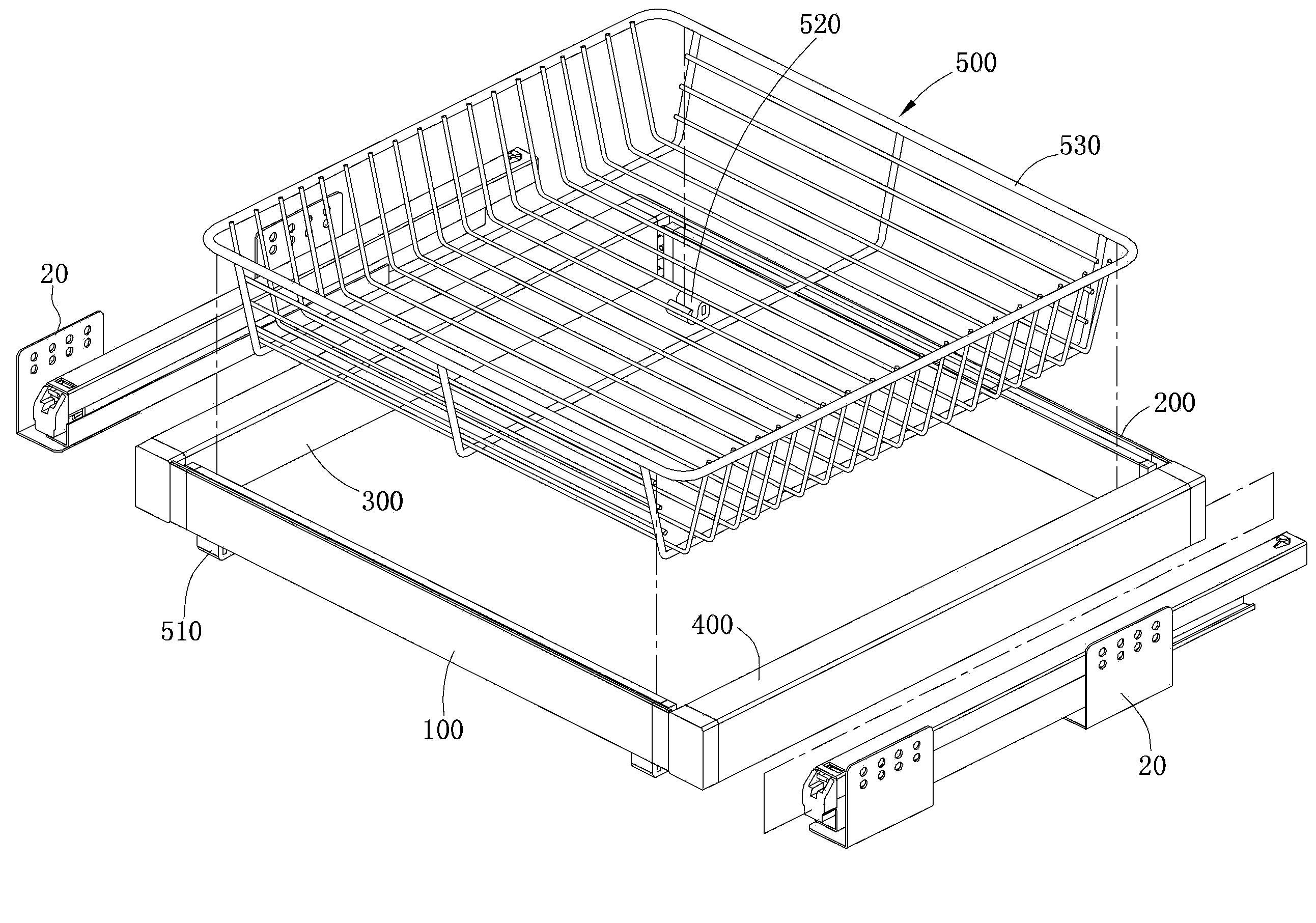
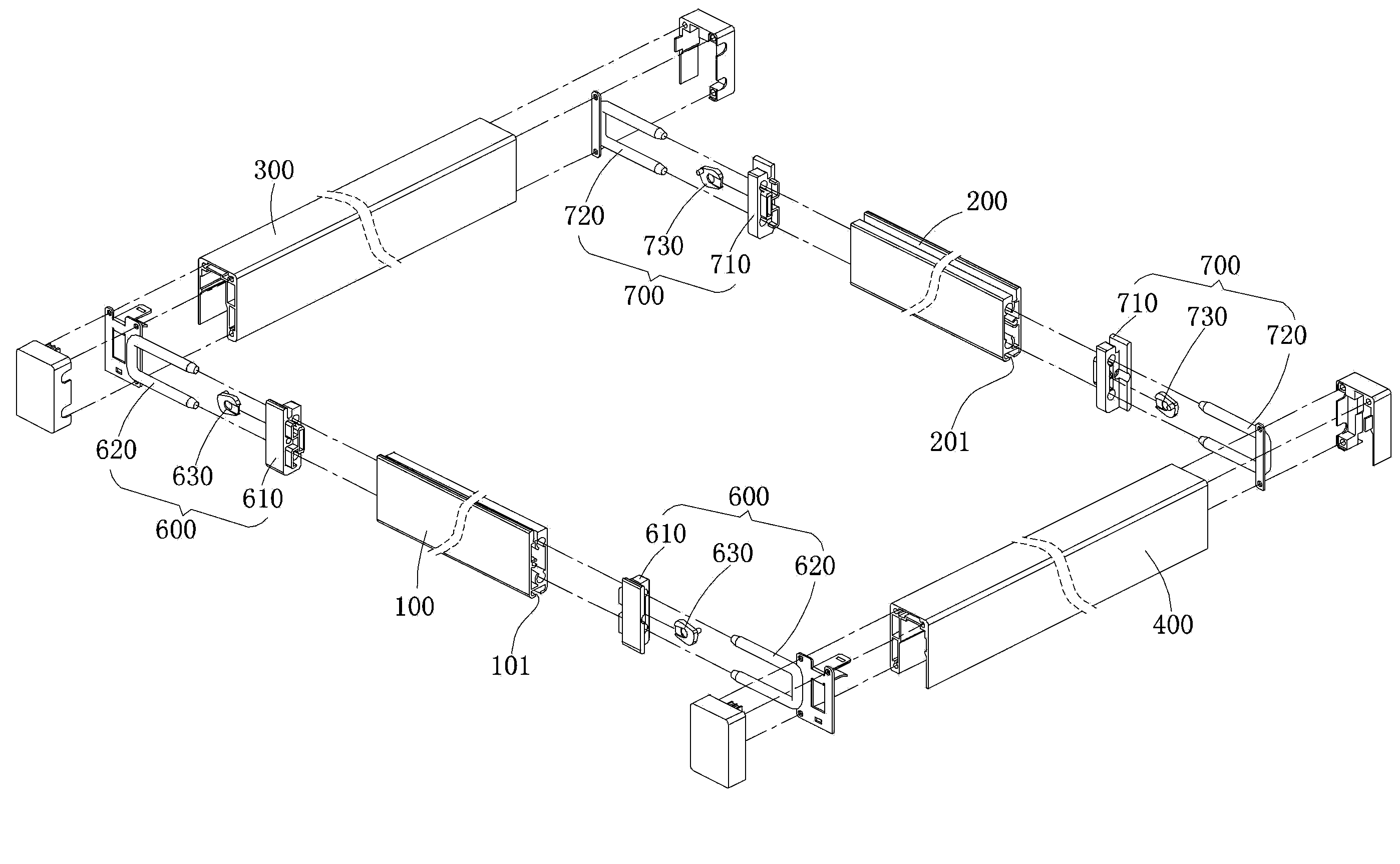
[0030] Please refer to Figure 1 to Figure 4 , figure 1 Is a three-dimensional schematic diagram of a modular frame according to the first embodiment of the present invention, figure 2 for figure 1 Partial exploded schematic diagram of image 3 for figure 2 The exploded schematic diagram of the front panel, rear panel, left and right components of Figure 4 for image 3 A plan exploded schematic diagram of the front plate and the carrying member of the

[0031] The modular frame 10 of this embodiment includes a front panel 100, a rear panel 200, a left side member 300, a right side member 400, and a carrying member 550. In addition, the modular frame 10 further includes two first coupling components 600 and two second coupling components 700.

[0032] The front plate 100, the rear plate 200, the left side member 300, the right side member 400, and the carrying member 550 enclose an accommodation space. The front plate 100 and the rear plate 200 are respectively located on opposi...


PUM


Abstract

A combined rack for connecting two sliding rails includes a front plate, a back plate, a left component, a right component and a carrying component. The front plate, the back plate, the left component, the right component and the carrying component together form an accommodation space. The left component and the right component are used for being installed on the two sliding rails respectively, in a slidable manner. The carrying component includes a carrying member, a front combining component and a back combining component. The lower edge of the front plate includes a back support structure, and the front combining component and the back combining component on opposite two sides of the carrying component are installed on the front support structure and the back support structure respectively.

Description

technical field [0001] The invention relates to a frame body, in particular to a combined frame body suitable for adjustable width. Background technique [0002] In order to allow the combined storage rack to be pulled out or pushed in from the cabinet, the combined storage rack is usually provided with a slide rail device on the left and right sides. The combined storage rack includes at least two sliding sets, multiple (front and rear) side members and a carrier. The two sliding sets are respectively sleeved on two slide rail devices, wherein the slide rail devices are set on the cabinet, and the slide sets Usually there is a combination part combined with the side member of the combined storage rack and a chute part for the slide rail, so that the sliding sleeve can be installed on the combined storage rack and can move relative to the slide rail to achieve relative The action of stretching or relative retraction so that the combined shelf can be pulled out or pushed in....

Claims


Application Information

Patent Timeline
IPC IPC(8): A47B96/06A47B88/04A47B88/49
CPCA47B2210/04A47B2088/0037A47B88/0014A47B96/00A47B88/941A47B2088/902A47B2088/421A47F5/0025A47F3/147A47B96/025A47F5/0093A47B2031/003A47F5/0031
Inventor 杨瑞链
Owner ULIKE
Why Eureka
Try Eureka