Commutator plastic sleeve separation mold

A commutator and plastic sleeve technology, applied in the field of molds, can solve problems such as low efficiency and high labor intensity

Active Publication Date: 2016-10-05
ANGU GRP CO LTD
View PDF6 Cites 0 Cited by
  • Summary
  • Abstract
  • Description
  • Claims
  • Application Information

AI Technical Summary

Problems solved by technology

[0002] In the production process of the commutator, it is usually first to punch a piece of independent commutator copper sheet, then arrange the commutator copper sheet in the plastic sleeve, and then put the commutator segment and the plastic sleeve together The commutator is injection molded together with bakelite powder or other matrix materials in the injection mold. The injection molded commutator is firmly combined with the plastic sleeve. The current method is to use a cutter to cut the outer circle of the plastic sleeve. Then it is peeled off from the outer surface of the commutator to complete the separation of the commutator and the plastic sleeve. The efficiency is low, the labor intensity is high, and the most important plastic sleeve is damaged and cannot be reused.

Method used


Image

  • Commutator plastic sleeve separation mold
  • Commutator plastic sleeve separation mold
  • Commutator plastic sleeve separation mold

Examples


Embodiment Construction

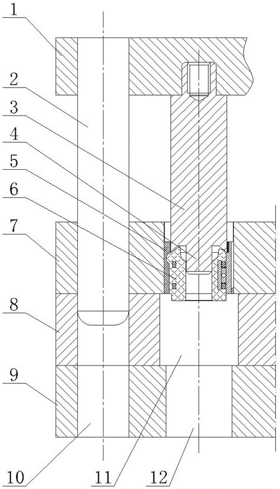
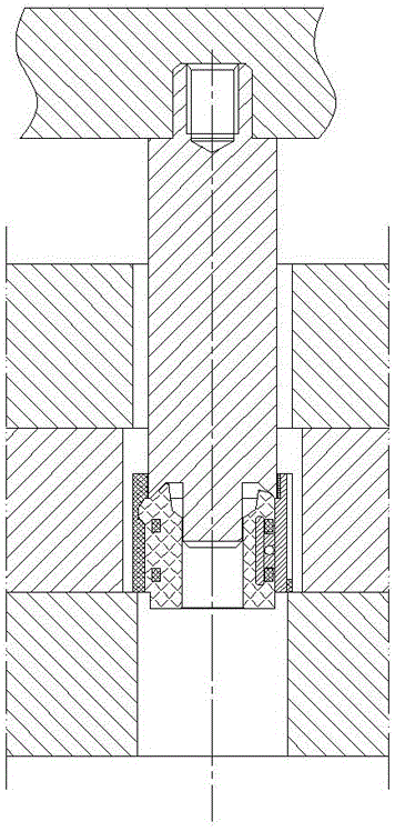
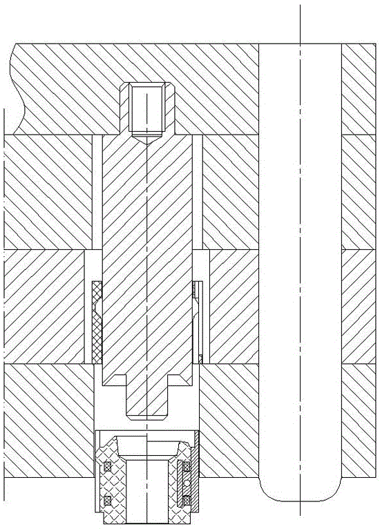
[0013] As shown in the figure, the commutator plastic sleeve separation mold of the present invention includes a movable upper mold 1 and a fixed lower mold. The bottom of the movable upper mold 1 is equipped with a thimble 3, and the diameter of the head of the thimble 3 is smaller than the diameter of the inner hole of the plastic sleeve 5. The head of the thimble 3 has a curved surface that matches the shape of the upper end surface of the commutator 6 and is provided with a plunger 4 for positioning the inner hole of the commutator 6. The fixed lower mold includes an upper backing plate 8 and a lower backing plate 9 that are fixedly connected , The upper backing plate 8 is provided with an upper through hole 11 that allows the commutator 6 and the plastic sleeve 5 combination to pass through at the same time. The diameter of the upper through hole 11 is larger than the outer diameter of the plastic sleeve 5, and the lower backing plate 9 is provided with the commutator 6 The...


PUM


Abstract

The invention discloses a plastic sleeve separation die of a reverser. The separation die comprises a movable upper die and a fixed lower die, and is characterized in that an ejection pin is arranged at the bottom of the movable upper die; the diameter of the ejection pin head is smaller than the diameter of an inner hole of the plastic sleeve; the fixed lower die comprises an upper pad and a lower pad which are fixedly connected; an upper through hole through which a combined body of the reverser and the plastic sleeve can penetrate is formed in the upper pad; the diameter of the upper through hole is greater than the excircle diameter of the plastic sleeve; a lower through hole through which the reverser can penetrate independently is formed in the lower pad; the diameter of the lower through hole is greater than that of the excircle of the reverser and is smaller than that of the excircle of the plastic sleeve. The plastic sleeve separation die is specially used for separating the reverser and the plastic sleeve after injection molding; the efficiency is improved; the labor intensity is alleviated; meanwhile, the most important is that the reutilization of the plastic sleeve is realized.

Description

Technical field [0001] The invention relates to a mold, in particular to a mold dedicated to separating a commutator from a plastic sleeve after injection molding. Background technique [0002] In the manufacturing process of the commutator, usually one piece of independent copper commutator is punched first, and then the commutator copper pieces are arranged in the plastic sleeve, and then the commutator pieces and the plastic sleeve are placed together. The commutator injection mold is combined with bakelite powder or other matrix materials for injection molding. The commutator after injection is firmly combined with the plastic sleeve. The current method is to use a cutter to cut the outer circle of the plastic sleeve. Then it is peeled from the outer surface of the commutator to complete the separation of the commutator and the plastic sleeve. The efficiency is low, the labor intensity is high, and the most important plastic sleeve is destroyed and cannot be reused. Summary ...

Claims


Application Information

Patent Timeline
Patent Type & Authority Patents(China)
IPC IPC(8): B29C45/17
CPCB29C45/4005
Inventor 陈辉陈林郑道武陈炜炜周新喆周晓军阮志清
Owner ANGU GRP CO LTD
Why Eureka
Try Eureka