injection molding machine
A technology for injection molding machines and moving parts, applied in the field of injection molding machines, can solve problems such as the balance destruction of the clamping force and the deterioration of the quality of the molded products.
- Summary
- Abstract
- Description
- Claims
- Application Information
AI Technical Summary
Problems solved by technology
Method used
Image

Examples
no. 1 Embodiment approach
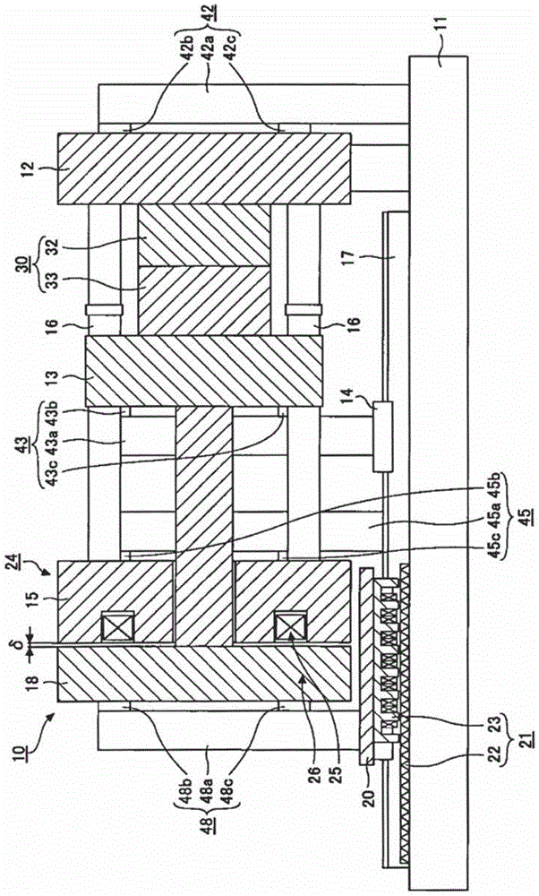
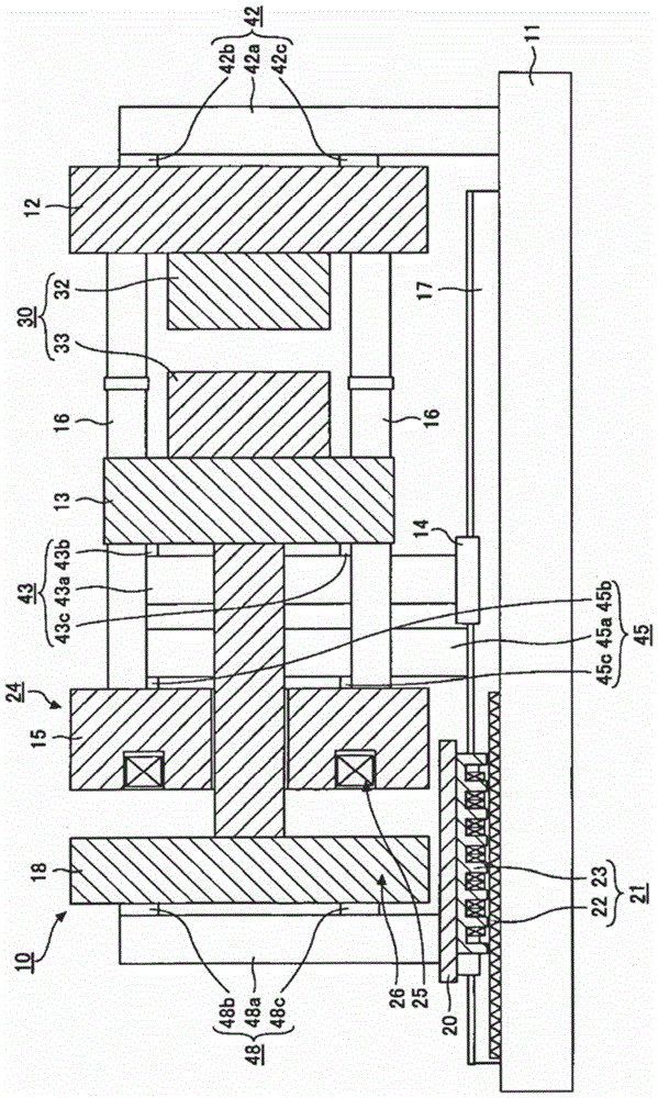
[0019] figure 1 It is a figure which shows the state at the time of completion|finish of mold closing of the injection molding machine concerning 1st Embodiment of this invention. figure 2 It is a figure which shows the state at the time of completion|finish of mold opening of the injection molding machine concerning 1st Embodiment of this invention.
[0020] The injection molding machine includes a mold clamping device 10 and the like that perform mold closing, mold clamping, and mold opening of the mold device 30 . The mold device 30 is constituted by, for example, a stationary mold 32 and a movable mold 33 . The mold device 30 is maintained at a predetermined temperature by a mold thermostat.
[0021] The mold clamping device 10 has a frame 11, a fixed platen 12 as a first fixed member, a movable platen 13 as a first movable member, a rear platen 15 as a second fixed member (and a mold clamping member), and a second The suction member 18 of the movable member, the linea...
no. 2 Embodiment approach
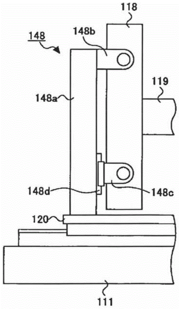
[0063] The suction member support portion of the present embodiment is different from the suction member support portion of the first embodiment in that it has a connection portion whose one end portion is relatively rotatably connected to the suction member. Hereinafter, the differences will be mainly described.
[0064] image 3 It is a figure which shows the adsorption|suction member and the adsorption|suction member support part which concern on 2nd Embodiment of this invention. The suction member support portion 148 supports the side surface of the suction member 118 . The suction member support portion 148 may be provided on the left and right sides of the suction member 118 so as to sandwich the center position of the suction member 118 (specifically, the center position of the attachment position of the rod 119 in the suction member 118 ). In addition, the adsorption member support portion 148 may support the surface (rear end surface) on the opposite side to the ads...
no. 3 Embodiment approach
[0079] The suction member support portion of the present embodiment has a plurality of connecting portions in which one end portion is connected to the suction member at different distances from the frame, and the other end portions of the plurality of connecting portions are relatively movable. It differs from the adsorption member support part of 1st Embodiment, and a different point is mainly demonstrated below.
[0080] Figure 4 It is a figure which shows the adsorption|suction member and the adsorption|suction member support part which concern on 3rd Embodiment of this invention. The suction member support portion 248 supports the side surface of the suction member 218 . The suction member support portions 248 may be provided on the left and right sides of the suction member 218 so as to sandwich the center position of the suction member 218 (specifically, the center position of the attachment position of the rod 219 in the suction member 218 ). In addition, the adsorp...
PUM
 Abstract
Description
Claims
Application Information
 - R&D
- Intellectual Property
- Life Sciences
- Materials
- Tech Scout
- Unparalleled Data Quality
- Higher Quality Content
- 60% Fewer Hallucinations
Browse by: Latest US Patents, China's latest patents, Technical Efficacy Thesaurus, Application Domain, Technology Topic, Popular Technical Reports.
© 2025 PatSnap. All rights reserved.Legal|Privacy policy|Modern Slavery Act Transparency Statement|Sitemap|About US| Contact US: help@patsnap.com