
A Clock Synchronization Method for Distributed Real-time Test System

A distributed real-time, clock synchronization technology, applied in time-division multiplexing systems, electrical components, multiplexing communications, etc. Guarantee efficiency, improve efficiency, avoid the effect of execution disorder

Active Publication Date: 2017-01-18
BEIHANG UNIV
View PDF4 Cites 0 Cited by
  • Summary
  • Abstract
  • Description
  • Claims
  • Application Information

AI Technical Summary

Problems solved by technology

The PTP protocol can quickly complete the clock synchronization operation between two nodes, but the synchronization speed between multiple nodes cannot meet the clock synchronization requirements of the distributed real-time test system
Moreover, clock synchronization between the master clock and multiple slave clocks not only takes up a lot of resources on the master clock node, but also takes up network resources for a long time and affects the communication of the system. For the test system, the cost brought during the test is even greater. is unacceptable
[0008] In the field of embedded software testing, testing is often required to be carried out under high real-time conditions, and the test tasks to be executed often require multiple executions in an accurate cycle. If clock synchronization is performed frequently, it will disturb the timer of the test system, resulting in execution cycle disorder
[0009] Therefore, there is a need for a method that, on the one hand, can quickly complete high-precision clock synchronization operations while consuming a small amount of resources; on the other hand, can avoid timing task execution disturbances caused by frequent clock adjustments during testing

Method used


Image

  • A Clock Synchronization Method for Distributed Real-time Test System
  • A Clock Synchronization Method for Distributed Real-time Test System

Examples


Embodiment Construction

[0038] In order to make the technical problems, technical solutions and advantages to be solved by the present invention clearer, the following will describe in detail with reference to the drawings and specific embodiments.

[0039] The invention relates to a clock synchronization method for a distributed real-time test system. On the one hand, the method can quickly complete high-precision clock synchronization operations while consuming a small amount of resources; on the other hand, it can avoid timing delays caused by frequent clock adjustments during the test Task execution disorder.

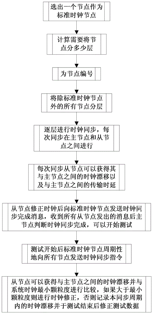
[0040] Such as figure 1 Shown, the concrete steps of the present invention in embodiment are as follows:

[0041] The clock synchronization steps before the test start are as follows:

[0042] Step 1: Select a node from all the nodes in the system as the standard clock node. Select standard clock nodes according to the following principles:

[0043] (1) If the test system includes a mast...


PUM


Abstract

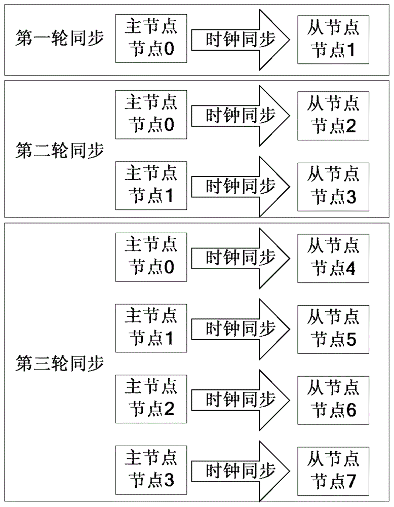
The invention relates to a distributed real-time test system clock synchronization method. The clock synchronization process is divided into a clock synchronization process before a test is started and a testing process, wherein before the test is started, a method similar to an IEEE 1588 clock synchronization method is utilized, clock synchronization accuracy between main nodes and auxiliary nodes is guaranteed, meanwhile, a layered synchronization method is utilized, indexes of the number of nodes synchronized on each round are increased, and system clock synchronization efficiency is guaranteed; in the synchronization process before the test is started, the auxiliary nodes can acquire transmission delay between the auxiliary nodes and the main nodes, so that clock synchronization efficiency in the test process is further improved based on the synchronization process before the test is started; eventually, in the testing process, the nodes acquire a clock drift, the clock drift is compared with a system clock minimum granularity, if the clock drift is smaller than the minimum granularity, the drift is recorded, and a time label of a test result is corrected after the test is finished. Thus, node timing task execution chaos caused by frequent correction of a clock is avoided.

Description

technical field [0001] The invention relates to a clock synchronization method of a distributed real-time test system, which belongs to the technical field of embedded software test. Background technique [0002] The application of embedded software in aerospace and other fields is expanding day by day, and the testing requirements for embedded software are becoming more and more urgent. On the one hand, in order to successfully complete the test task, the embedded software test system must be able to complete the scheduled task accurately at the specified time point; on the other hand, as the complexity of the embedded system itself becomes stronger and stronger, the The ability of the test system to accommodate the load also puts forward higher and higher requirements accordingly. The test system with a distributed architecture can evenly distribute the load to each node to run without interfering with each other. [0003] The distributed real-time test system needs to co...

Claims


Application Information

Patent Timeline
Patent Type & Authority Patents(China)
IPC IPC(8): H04J3/06
Inventor 杨顺昆刘斌司维
Owner BEIHANG UNIV
Learn More