
Redundancy control device, equipment redundancy system and method based on real-time Ethernet

A technology of control equipment and redundant control, applied in transmission systems, digital transmission systems, data exchange networks, etc., can solve problems such as the failure of the standby main control equipment to be activated and the function of the standby main control equipment cannot be verified, and achieve The effect of eliminating potential safety hazards

Active Publication Date: 2018-05-25
CSR ZHUZHOU ELECTRIC LOCOMOTIVE RES INST
View PDF3 Cites 0 Cited by
  • Summary
  • Abstract
  • Description
  • Claims
  • Application Information

AI Technical Summary

Problems solved by technology

[0005] In view of this, the object of the present invention is to provide a real-time Ethernet-based redundant control device, equipment redundancy system and method, to overcome the fact that the standby main control equipment cannot be activated when the existing main control equipment is normal and fault-free. , resulting in the problem that the function of the standby master control device cannot be verified for a long time

Method used


Image

  • Redundancy control device, equipment redundancy system and method based on real-time Ethernet
  • Redundancy control device, equipment redundancy system and method based on real-time Ethernet
  • Redundancy control device, equipment redundancy system and method based on real-time Ethernet

Examples


Embodiment 1

[0057] The first embodiment discloses a real-time Ethernet-based redundant control device, which is used to control the first control device of the network system, so that the first control device becomes the main control device or backup master of the network system. control device, the network system includes a first control device, a second control device and other devices. Specifically, the embodiment of the present invention applies the redundant control device to the train network control system, by controlling the corresponding control devices in the train network control system (including two mutually redundant control devices), making it a train network The master or backup master of the control system.

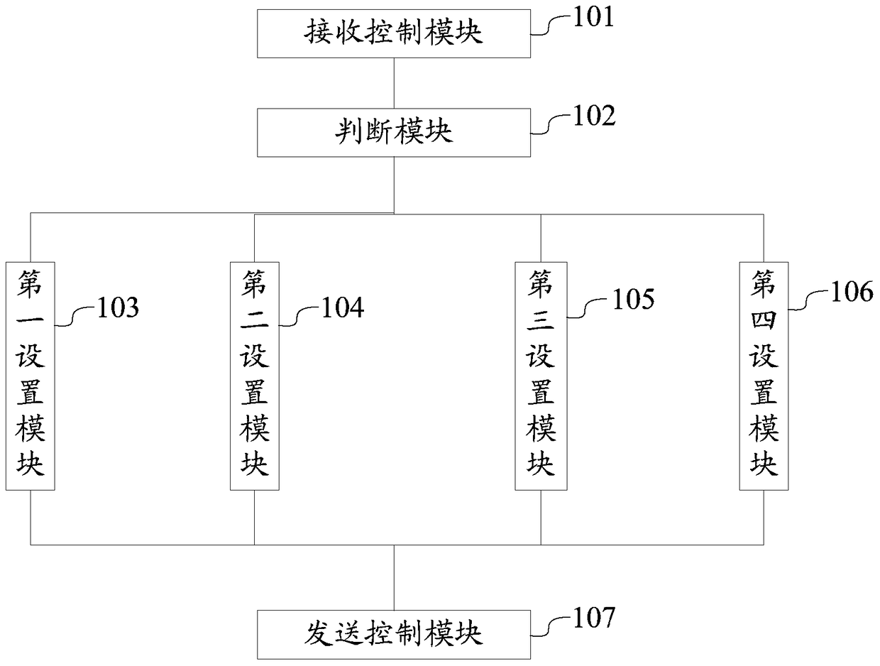
[0058] See figure 1 The redundancy control device in this embodiment includes a receiving control module 101 , a judging module 102 , a first setting module 103 , a second setting module 104 , a third setting module 105 , a fourth setting module 106 and a sending co...

Embodiment 2

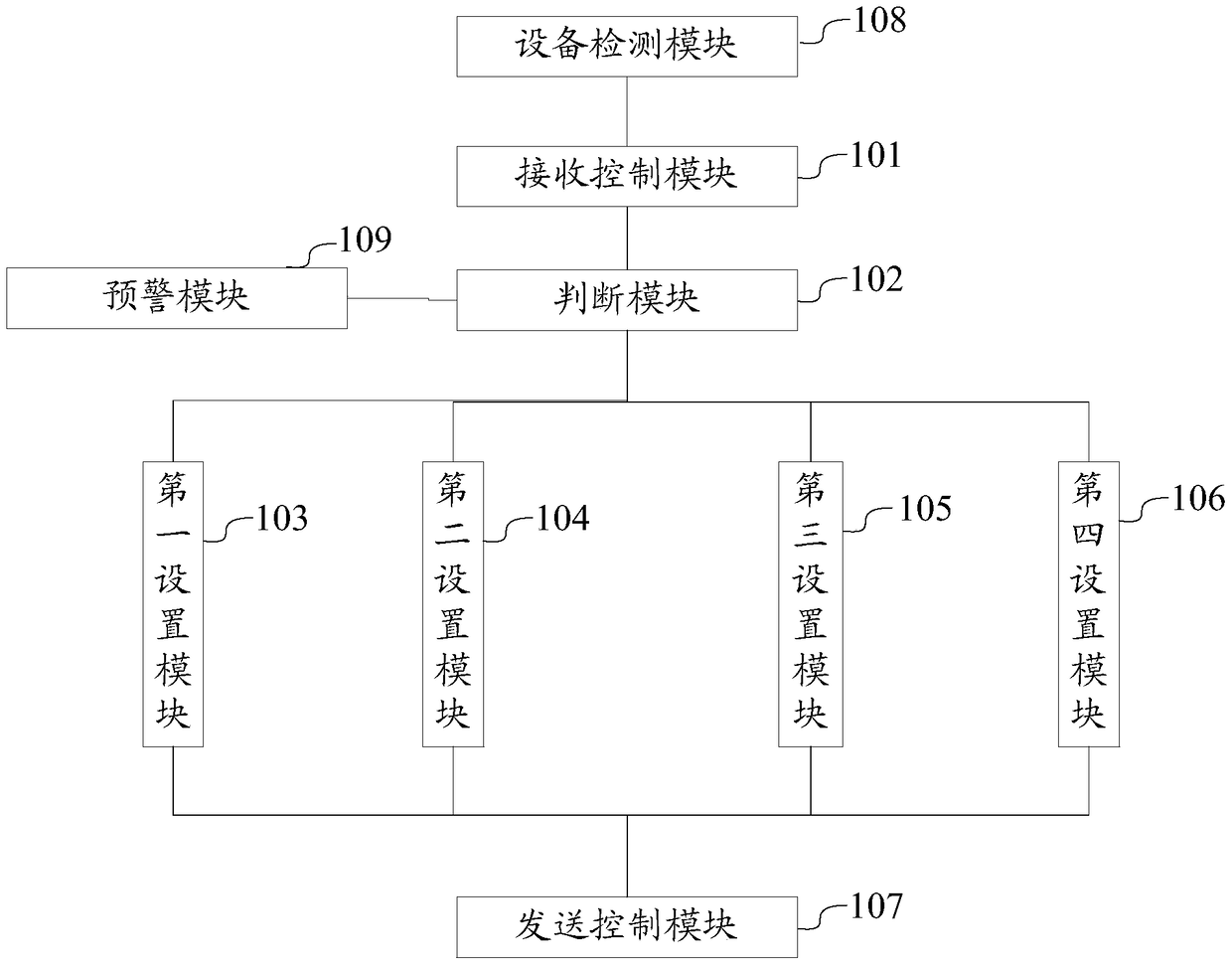
[0075] This second embodiment continues to expand the redundant control device of the first embodiment, please refer to figure 2 , the real-time Ethernet-based redundant control device further includes an equipment detection module 108 and an early warning module 109 .

[0076] The device detection module 108 is configured to detect whether the first control device is faulty during the startup process of the first control device, and generate fault information of the first control device according to the detection result.

[0077]Wherein, the fault information detected by the first control device is added to the first redundant state information of the first control device to provide a basis for setting the state of the subsequent control device. Correspondingly, the second redundant state information is also expanded and added with the fault information of the second control device. The fault information detected by the device detection module 108 is specifically a device f...

Embodiment 3

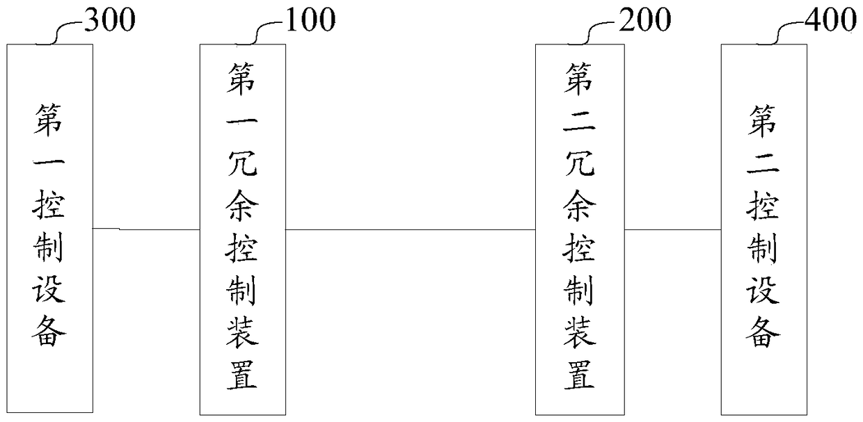
[0083] Embodiment 3 discloses a real-time Ethernet-based equipment redundancy system, please refer to image 3 , the system includes two redundant control devices as disclosed in Embodiment 1 or Embodiment 2, respectively set as the first redundant control device 100 and the redundant control device 200, and also includes the first control device 300, the second control device Device 400.

[0084] Wherein, the first redundant control device 100 and the second redundant control device 200 interact with each other, and the first redundant control device 100 controls the first control device 300, and the second redundant control device 200 controls the second control device 400 Controlling is performed so that the first control device 300 and the second control device 400 are redundant to each other, serving as a master control device or a backup master control device of the network system.

[0085] The device redundancy system of the present invention uses random numbers to sel...


PUM


Abstract

The invention discloses a real-time Ethernet based redundancy control device, as well as a device redundancy system and method. The system comprises a first control device, a second control device, a first redundancy control device and a second redundancy control device, wherein the first redundancy control device and the second redundancy control device are used for controlling the first control device and the second control device respectively, so as to enable the first control device and the second control device to be adopted as a main-control device or a standby main-control device of a network system; random numbers are adopted to select the main-control device; particularly, a first random number of the first control device and a second random number of the second control device are generated at the given replacing moment respectively; by comparing the two random numbers, the follow-up two redundancy control devices are used for controlling the corresponding control device as the main-control device or the standby main-control device. Therefore, the random numbers are adopted to select the main-control device, and each control device has an equivalent probability to be adopted as the main-control device, so that timely verification and fault treatment of each control device can be realized subsequently, and potential safety hazard is eliminated.

Description

technical field [0001] The invention belongs to the technical field of industrial control and field control, and in particular relates to a real-time Ethernet-based redundant control device, equipment redundant system and method. Background technique [0002] With the development of high-speed trains and automation, the train network control system has become more and more important. The main control equipment is the core equipment of the train network control system, which is responsible for the logic control of the entire train and the management and monitoring of other on-board equipment, and is the control center of the entire train. [0003] In order to ensure the safe and reliable operation of the train and prevent the entire train network control system from being paralyzed due to the failure of the main control equipment, it is necessary to formulate a redundancy scheme for the main control equipment to be redundant. For this reason, two control devices with the sam...

Claims


Application Information

Patent Timeline
Patent Type & Authority Patents(China)
IPC IPC(8): H04L12/24H04L12/28H04L1/22
Inventor 杨卫峰冯江华唐军肖家博邹智荣李思源
Owner CSR ZHUZHOU ELECTRIC LOCOMOTIVE RES INST
Learn More