Supercharge Your Innovation With Domain-Expert AI Agents!

Lubricated machine element and method for lubrication

A technology of mechanical components and lubricating grease, applied in the direction of engine components, mechanical equipment, bearing components, etc., can solve complex and time-consuming problems, achieve the effect of simple relubrication and reduce waste

Inactive Publication Date: 2014-10-01
AB SKF
View PDF10 Cites 1 Cited by
  • Summary
  • Abstract
  • Description
  • Claims
  • Application Information

AI Technical Summary

Problems solved by technology

However, to prevent premature wear and damage, manufacturers recommend removing the old grease and replacing it with new grease on a periodic basis, which can be a complex and time-consuming process as it often requires equipment to be dismantled and carefully to clean

Method used


Image

  • Lubricated machine element and method for lubrication
  • Lubricated machine element and method for lubrication

Examples


Embodiment Construction

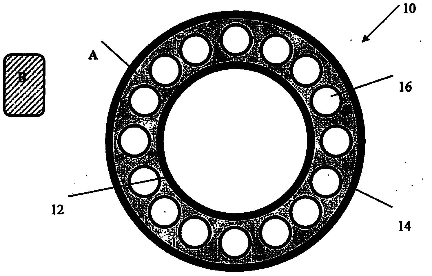
[0036] figure 1 An example of a machine element 10 is schematically shown, namely a rolling element bearing, which may range in size from 10 mm diameter to several meters in diameter, and have a load capacity ranging from tens of grams to several thousand tons. That is, the bearing component 10 can be of any size and have any load capacity. The bearing component 10 has an inner ring 12 , an outer ring 14 and a set of rolling elements 16 .

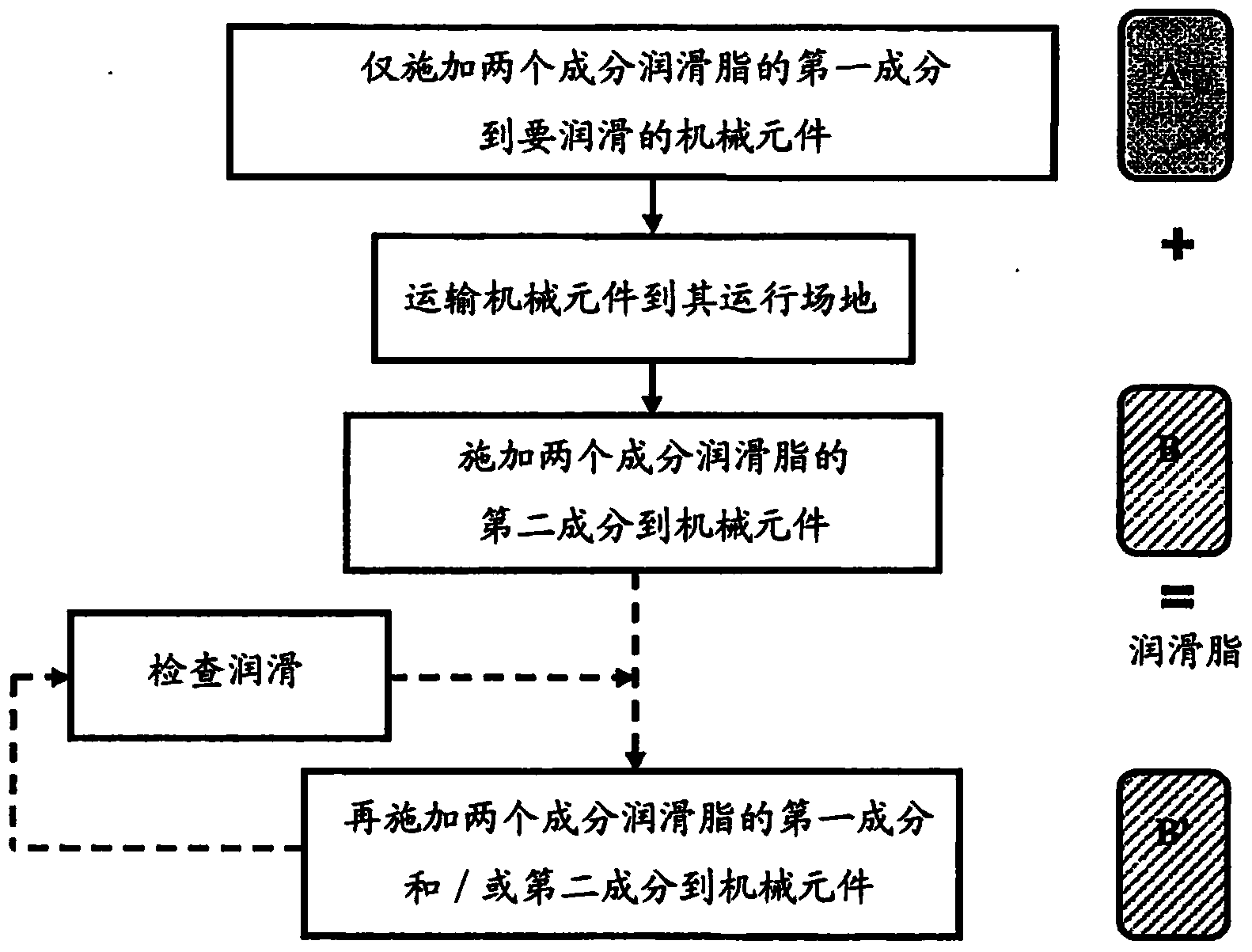
[0037] Grease must be provided between the rolling elements 16 and the inner ring 12 and outer ring 14 to lubricate the rolling element bearing 10 . Therefore, a two-component grease package is selected based on the bearing's rotational speed, service temperature range, operating noise requirements, relubrication intervals, seals, starting torque, and / or environmental influences.

[0038] The first component A comprises a thickener, such as at least one of the following: polymeric thickener, polypropylene, polyethylene, polyethylene glyco...


PUM


Abstract

A machine element (10) that only comprises a first component (A) of a two-component grease that comprises a first component (A) comprising a thickener, and a second component (B) comprising a fluid lubricant, whereby the two-component grease is obtained by mixing together the first and second components (A and B).

Description

technical field [0001] The present invention relates to mechanical elements and methods of providing such mechanical elements. Background technique [0002] In terms of lubricating oils, the term grease is used to describe a semi-solid lubricant consisting of a thickener, typically soap, emulsified with mineral or vegetable oil and / or other liquid lubricants. Greases have a very high initial viscosity, which decreases when shear is applied to give the effect of oil lubrication, which is essentially the same viscosity as the base oil used in the grease. Grease is applied to mechanical parts that are infrequently lubricated and located where the oil cannot stay. [0003] Grease also protects mechanical components, it lubricates against corrosion and wear, it helps dissipate heat, seals out solid and liquid contaminants, and reduces noise. Proper lubrication allows the equipment to run smoothly and continuously, with only mild wear, without undue stress or seizures on compone...

Claims


Application Information

Patent Timeline
Patent Type & Authority Applications(China)
IPC IPC(8): F16C33/66C10M111/00C10M169/02F16N15/00C10N40/02C10N50/10
CPCF16C33/6688C10M2229/006C10N2240/04C10M2209/1026C10M2205/0285C10M2203/1006C10M2209/1023C10M2205/0213C10M111/00F16N15/00C10M2215/1026C10M2207/401F16C33/664F16C33/6633C10M2207/2805C10N2240/08C10N2230/06C10N2250/10F16N17/00C10M169/02C10N2240/02C10N2220/021C10M2207/1256C10N2020/04C10N2030/06C10N2040/02C10N2040/04C10N2040/08C10N2050/10
Inventor I.斯特兰德尔F.费德拉尔斯
Owner AB SKF
Features
  • R&D
  • Intellectual Property
  • Life Sciences
  • Materials
  • Tech Scout
  • Unparalleled Data Quality
  • Higher Quality Content
  • 60% Fewer Hallucinations
Learn More