Handle fixing structure

A technology for fixing the structure and handle, which is applied in the direction of the handle of the wing fan, the spherical handle of the wing fan, the building structure, etc.

Active Publication Date: 2014-10-08
ZHEJIANG SANXING NEW MATERIALS
View PDF5 Cites 0 Cited by
  • Summary
  • Abstract
  • Description
  • Claims
  • Application Information

AI Technical Summary

Problems solved by technology

[0004] In order to solve the above technical problems, the object of the present invention is to provide a handle fixing structure, which solves the problem that the handle holes cannot be installed if they are not concentric, the handle position can be adjusted, and it is easy to replace

Method used


Image

  • Handle fixing structure
  • Handle fixing structure
  • Handle fixing structure

Examples


Embodiment 1

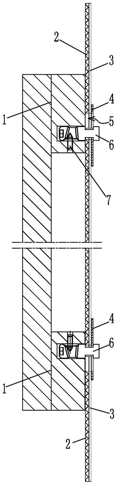
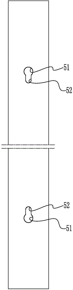
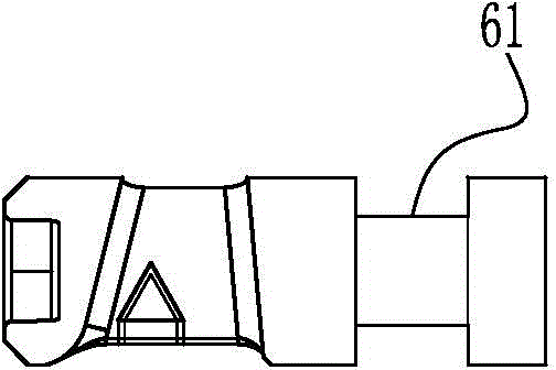
[0013] Such as figure 1 The shown handle fixing structure includes a handle assembly 1 and a door shell assembly. The door shell assembly includes an outer glass 2, an aluminum alloy frame 3, and an inner reinforcing iron 4. The door shell assembly is provided with two special-shaped through holes 5 , The special-shaped through hole 5 penetrates the corresponding positions on the outer glass 2, the aluminum alloy frame 3 and the inner reinforcing iron 4, such as figure 2 As shown, the special-shaped through hole 5 includes a large-aperture end 51 and a small-aperture end 52; the handle assembly 1 is connected to two special-shaped through holes 5 on the door shell assembly through two connecting posts 6, such as image 3 As shown, one end of the connecting column 6 inserted into the special-shaped through hole 5 has an annular groove 61. The outer diameter of the connecting column 6 in the annular groove 61 matches the outer diameter of the special-shaped through hole 5 at the s...


PUM


Abstract

The invention discloses a handle fixing structure which comprises a handle assembly and a door shell assembly. The handle assembly is connected with two special-shaped through holes in the door shell assembly through two connecting columns. The end, inserted into the corresponding special-shaped through hole, of each connecting column is provided with an annular groove. The outer diameters, at the portion of the annular grooves, of the connecting columns are matched with the outer diameters of the small-bore ends of the special-shaped through holes. The outer diameters, at the two side portions of the annular grooves, of the connecting columns are larger than the outer diameters of the small-bore ends of the special-shaped through holes and smaller than the outer diameters of the large-bore ends of the special-shaped through holes. The end, inserted into the handle assembly, of each connecting column is fixedly connected with the handle assembly. The two special-shaped through holes in the door shell assembly are arranged in a mirror-symmetry mode. The distance between the centers of the two large-bore ends is larger than the distance between the centers of the two small-bore ends. The distance between the centers of the two small-bore ends is matched with the installation distance of the two connecting columns on the handle assembly. According to the scheme, the problem that installation cannot be achieved due to the fact that handle holes are not concentric is solved, the position of a handle can be adjusted, and disassembly and replacement are convenient.

Description

Technical field [0001] The invention relates to a handle fixing structure. Background technique [0002] In the prior art, screws are used to fix the handle assembly from the inside of the door. The screws need to pass through the inner reinforcing iron, frame, and outer glass from inside the frame of PVC or aluminum alloy, and then fix the handle assembly. Processing, and the size requirements are high, otherwise the position of the glass hole cannot be guaranteed to be concentric. Moreover, for the beauty of the door body and easy installation, the screws are inserted into the PVC door seal groove on the rear side, so the position of the handle is basically fixed and cannot be moved left or right. Moreover, this structure is cumbersome when the handle is replaced, and it is necessary to remove the door seal and remove the screws from the inside of the door body. [0003] The patent document with the publication number CN201050919Y discloses a door handle installation structure....

Claims


Application Information

Patent Timeline
Patent Type & Authority Applications(China)
IPC IPC(8): E05B1/00
Inventor 杨敏杨玉敏
Owner ZHEJIANG SANXING NEW MATERIALS
Why Eureka
Try Eureka