Close-fitted heat radiation fin and heat pipe structure

A technology of heat dissipation fins and heat pipes, which is applied in the combined application field of heat dissipation fins and heat pipes, and can solve the problem that heat dissipation fins and heat pipes cannot achieve urgent combination effects

Active Publication Date: 2014-10-08
DONG GUAN HAN XU HARDWARE & PLASTIC TECH CO LTD
View PDF13 Cites 0 Cited by
  • Summary
  • Abstract
  • Description
  • Claims
  • Application Information

AI Technical Summary

Problems solved by technology

[0005] In view of this, the present invention aims at the deficiencies in the prior art, and its main purpose is to provide a heat dissipation fin and a heat pipe that are closely matched, which can effectively solve the problem that the existing heat dissipation fin and heat pipe cannot achieve the tight combination effect. The problem

Method used


Image

  • Close-fitted heat radiation fin and heat pipe structure
  • Close-fitted heat radiation fin and heat pipe structure
  • Close-fitted heat radiation fin and heat pipe structure

Examples


Embodiment Construction

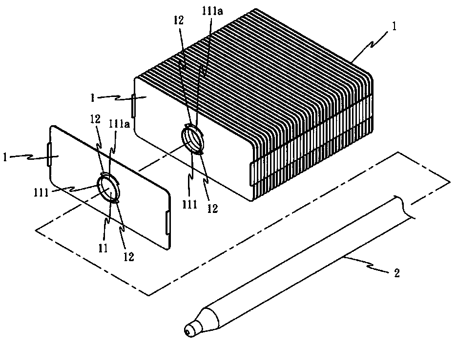
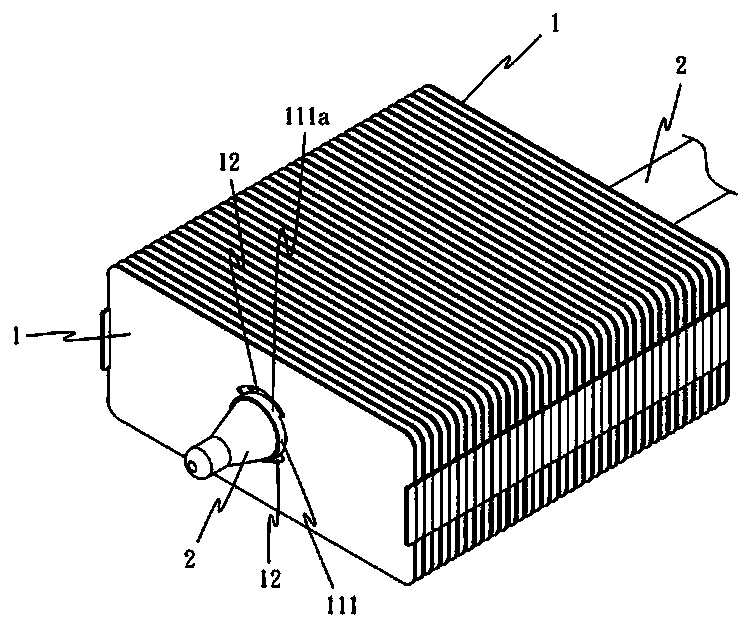
[0035] Such as Figure 1 to Figure 5 As shown, it shows the specific structure of the present invention, which mainly includes a plurality of cooling fins 1 and a heat pipe 2, and wherein:

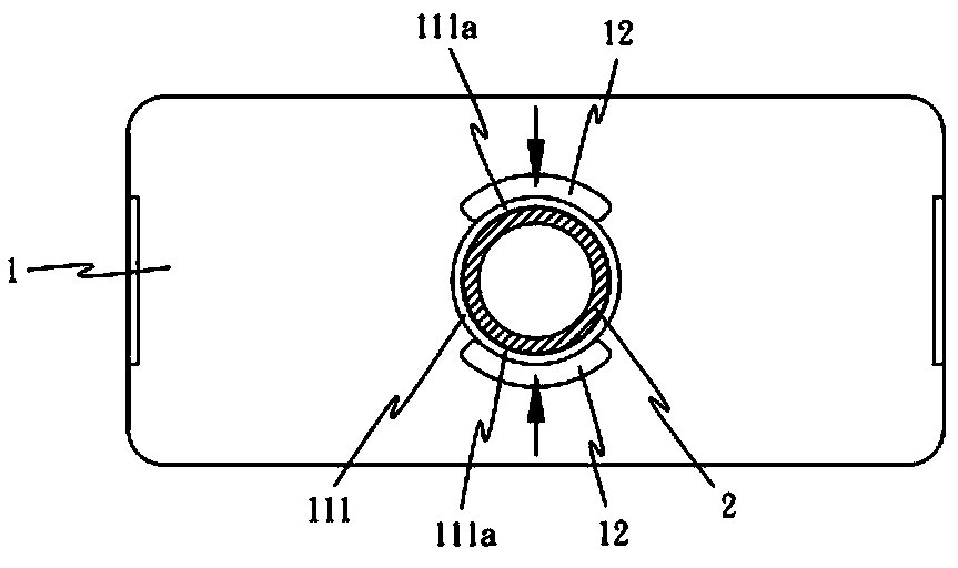
[0036] A plurality of cooling fins 1 are arranged in series, and each cooling fin 1 is provided with at least one through hole 11, and the through hole 11 has an extended protruding ring 111, and the protruding ring 111 is provided with an adjoining one on both symmetrical sides. The arc-shaped hole 12 separates the partial ring walls 111 a on both sides of the protruding ring 111 from the main body of the cooling fin 1 .

[0037] The heat pipe 2 runs through the through holes 11 of the series-parallel heat dissipation fins 1 .

[0038] Utilize above-mentioned plural heat dissipation fins 1 and heat pipe 2, system heat pipe 2 runs through the through hole 11 of heat dissipation fin 1 (such as figure 2 and image 3 ), and then stamp the local ring walls 111a on both sides of the convex ...


PUM


Abstract

The invention discloses a close-fitted heat radiation fin and heat pipe structure which mainly comprises a complex number of heat radiation fins and a heat pipe, wherein each heat radiation fin is provided with at least one through hole; the through hole is provided with a bulge loop; adjacent arched holes are respectively formed in two symmetric sides of the bulge loop, so that partial circular walls on two sides of the bulge loop are separated from a main body of heat radiation fins; the complex number of the heat radiation fins are connected in series and parallel; the heat pipe penetrates through the through holes of the heat radiation fins; the partial circular walls on two sides of the bulge loop are further stamped to deform, and then the heat radiation fins are closely fitted with the heat pipe.

Description

technical field [0001] The invention relates to a combined application of a heat dissipation fin and a heat pipe, especially a heat dissipation fin and a heat pipe that can be tightly matched. Background technique [0002] It is known that for the combination of heat dissipation fins and heat pipes in radiators, welding is commonly used to achieve the purpose of combining heat dissipation fins and heat pipes, but the welding operation is not environmentally friendly, and the process is cumbersome, and thermal resistance will also occur , so it is necessary to improve. [0003] Such as the No. 094142916 (I270339) Chinese Taiwan invention patent, which provides a kind of pressing forming method of heat pipe and heat dissipation fin, mainly opens a through hole in the heat dissipation fin, the through hole has a ring protruding wall, and then cooperates with the jig And side pressure technology, after the heat pipe is penetrated into the through hole, the component is deformed...

Claims


Application Information

Patent Timeline
Patent Type & Authority Applications(China)
IPC IPC(8): F28D15/04F28F1/30F28F9/26
CPCF28D15/0275F28F1/24F28F2275/12F28D15/02H01L23/427H05K7/20
Inventor 黄崇贤
Owner DONG GUAN HAN XU HARDWARE & PLASTIC TECH CO LTD
Why Eureka
Try Eureka