
Stepped wire coil pay-off rack

A stepped and pay-off rack technology, which is applied in the direction of coil manufacturing, electrical components, and conveying filamentous materials, can solve the problems of different traction force, excessive force on the wires, poor stacking flatness of the wires, etc., and achieve dimension damage Improvement of environment, elimination of wire wear, and improvement of safety

Inactive Publication Date: 2014-10-08
JIANGSU JURONG UNITED COPPER MATERIAL
View PDF4 Cites 5 Cited by
  • Summary
  • Abstract
  • Description
  • Claims
  • Application Information

AI Technical Summary

Problems solved by technology

The more wire reels, the larger the sector, the greater the friction of the outer end of the wire by the clamp, the more serious the wear, and the worse the flatness of the wire superimposition
In addition, the position of each wire winding on the wire reel cannot be the same, resulting in different tension of each wire, and the traction force is completely different. It often happens that a certain wire is under too much force and has a small waist and a deviation in size.

Method used


Image

  • Stepped wire coil pay-off rack

Examples


Embodiment Construction

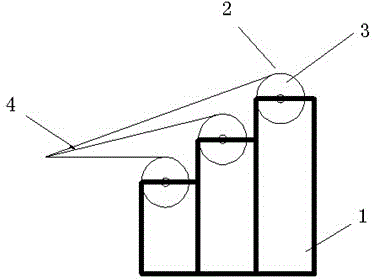
[0010] A stepped reel pay-off rack, the pay-off rack includes a stepped support 1, a pay-off device 2 for installing a reel 3 is provided on each step of the stepped support, and the pay-off device can move left and right set on a stepped stand. The stepped support is provided with three layers of steps, and the heights of the three layers of steps are arranged in equal difference. A group of parallel laying-off devices are horizontally arranged on each step.

[0011] The wire reels are operated separately, and there is no need for multiple wire reels to be connected in series to operate as a whole, which greatly improves the safety. A ladder-type pay-off frame is adopted, multiple wire reels are placed in parallel, multiple wires 4 are gathered and stacked along a straight line, and multiple wire reels are paid off individually, with uniform traction.

[0012] The use of the invention basically eliminates wire wear, greatly improves the flatness of wire superimposition; the...


PUM


Abstract

The invention discloses a stepped wire coil pay-off rack. The pay-off rack comprises a stepped bracket, wherein a pay-off device for mounting a wire coil is arranged on each layer of step of the stepped bracket; each pay-off device is arranged on the stepped bracket in a manner of moving leftwards and rightwards. By adopting the pay-off rack, the abrasion of wires is avoided by and large, the smoothness in overlapping of the wires is greatly improved, the wires are stressed uniformly, and the conditions of small waistline and size deviation are obviously improved.

Description

technical field [0001] The invention relates to a transformer and its matching products, in particular to a ladder-type reel pay-off frame. Background technique [0002] As the carrier for the production of electromagnetic wire, the wire reel is widely used in large quantities, especially the paper-wrapped composite winding wire requires multiple wire reels to be unwound at the same time, and the requirements are more stringent. At present, it is common to use one roller to connect multiple wire reels in series at the same time to carry out the pay-off operation. The multiple wires are collected and stacked together by clamps like fans, and then wrapped with insulating paper tape to fix them. The more wire reels, the larger the sector, the greater the friction of the outer end of the wire by the clamp, the more serious the wear, and the worse the flatness of the wire superimposition. In addition, the position of each reel of wires winding on the wire reel cannot be the same...

Claims


Application Information

Patent Timeline
Patent Type & Authority Applications(China)
IPC IPC(8): H01F41/06B65H49/32H01F41/096
Inventor 刘松
Owner JIANGSU JURONG UNITED COPPER MATERIAL
Learn More