Back pressure automatic lock controller

A lock controller and automatic technology, applied in electrical components, emergency protection circuit devices, etc., can solve problems such as personal electric shock death

Inactive Publication Date: 2017-01-04
尤田柱
View PDF5 Cites 0 Cited by
  • Summary
  • Abstract
  • Description
  • Claims
  • Application Information

AI Technical Summary

Problems solved by technology

[0006] In order to solve the problem of the lack of existing anti-power transmission technology and the passive management and the frequent occurrence of personal electric shock and death accidents, the invention provides an automatic anti-voltage lock controller

Method used


Image

  • Back pressure automatic lock controller
  • Back pressure automatic lock controller
  • Back pressure automatic lock controller

Examples


specific Embodiment approach 1

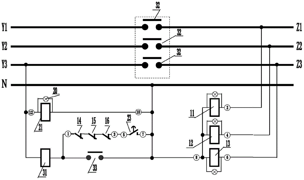
[0050] Specific implementation mode one, such as image 3 and Figure 5 As shown, when the low-voltage switch is an AC contactor 3 , the AC contactor 3 mainly includes: an AC contactor closing coil 31 , three AC contactor main contacts 32 , and an AC contactor normally open auxiliary contact 33 . The terminals ②, ④, ⑥ of the three phase-separated voltage measuring relays 11, 12, 13 of the locking controller of the present invention are respectively connected to the load users of the low-voltage power distribution lines controlled by the main contacts 32 of the three AC contactors In the voltage circuit of each phase on the side, it is used to measure the reverse voltage. The common terminal ⑧ of the three phase-separated voltage measurement relays 11, 12, and 13 is connected to the zero phase; the terminal of the voltage monitoring delay relay 21 It is directly connected to the one-phase voltage circuit on the side of the distribution transformer, and the other terminal ⑩ of...

specific Embodiment approach 2

[0058] Specific Embodiment 2. The feedback voltage measurement locking logic of the locking controller of the present invention can be designed in the smart circuit breaker 4 as an extended application of the protection function, and its electrical wiring or logical relationship will be attributed to the internal principle of the smart circuit breaker at the same time wiring or smart protection logic. Such as Figure 4 As shown, when the low-voltage switch is an intelligent circuit breaker 4, the intelligent circuit breaker 4 mainly includes: an intelligent circuit breaker closing coil 41, an intelligent circuit breaker opening coil 42, three intelligent circuit breaker main contacts 43, and an intelligent circuit breaker normally The auxiliary contact 44 is opened, and the auxiliary contact 45 of the intelligent circuit breaker is normally closed. The working voltage circuit of the smart circuit breaker 4 is determined by the component manufacturer, for the convenience of in...


PUM


Abstract

The anti-voltage automatic locking controller relates to the field of low-voltage anti-power transmission prevention and control, and solves the problem of frequent personal electric shock fatal accidents caused by the lack of existing technology. The reverse voltage blocking mechanism includes three voltage measurement relays, three reverse voltage warning lights, three measurement relay normally closed contacts for closing and blocking control of the low-voltage switch, and implementation of opening and blocking control for the low-voltage switch The three normally open contacts of the measurement relay; the delay opening and locking mechanism includes a delay relay, and the voltage monitoring lights connected in parallel at both ends of the delay relay, and the three normally open contacts of the measurement relay work together to open the low-voltage switch. The normally closed contact of the time delay relay for locking control and the normally open contact of the time delay relay for closing and locking control of the low voltage switch work together with the normally closed contacts of the three measuring relays. The invention is used to monitor the distribution direction of the power supply, and prevent the reverse transmission of power from the user end to the high-voltage distribution line, which will cause personal electric shock casualties to maintenance workers.

Description

technical field [0001] The invention relates to the technical field of low-voltage anti-power transmission monitoring and locking automatic prevention and control, in particular to an anti-voltage automatic locking controller, which is used for the low-voltage side (including the user end) of the distribution transformer of the power supply system, and provides low-voltage users through low-voltage distribution lines, Distribution transformers, reverse power transmission to distribution transformers and high-voltage distribution lines for prevention and control. Background technique [0002] The normal power consumption of power users comes from the high-voltage power distribution lines of the power supply system. When the high-voltage power distribution lines are out of power for maintenance, users who are in urgent need of electric energy will use their own power supplies to provide power for electrical equipment, which may make low-voltage power supplies If it is sent bac...

Claims


Application Information

Patent Timeline
Patent Type & Authority Patents(China)
IPC IPC(8): H02H11/00
Inventor 尤田柱
Owner 尤田柱
Why Eureka
Try Eureka