Transmission line rf applicators for plasma chambers

一种等离子体、等离子的技术,应用在离子体放电领域,能够解决天线不理想等问题

Active Publication Date: 2017-12-05
APPLIED MATERIALS INC
View PDF8 Cites 0 Cited by
  • Summary
  • Abstract
  • Description
  • Claims
  • Application Information

AI Technical Summary

Problems solved by technology

Non-uniformity increases with antenna length, so such antennas are less ideal for large plasma chambers

Method used


Image

  • Transmission line rf applicators for plasma chambers
  • Transmission line rf applicators for plasma chambers
  • Transmission line rf applicators for plasma chambers

Examples


Embodiment Construction

[0038] Best Mode for Carrying Out the Invention

[0039] 1. Dual Conductor RF Applicator

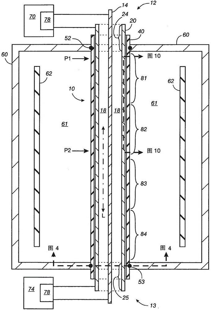
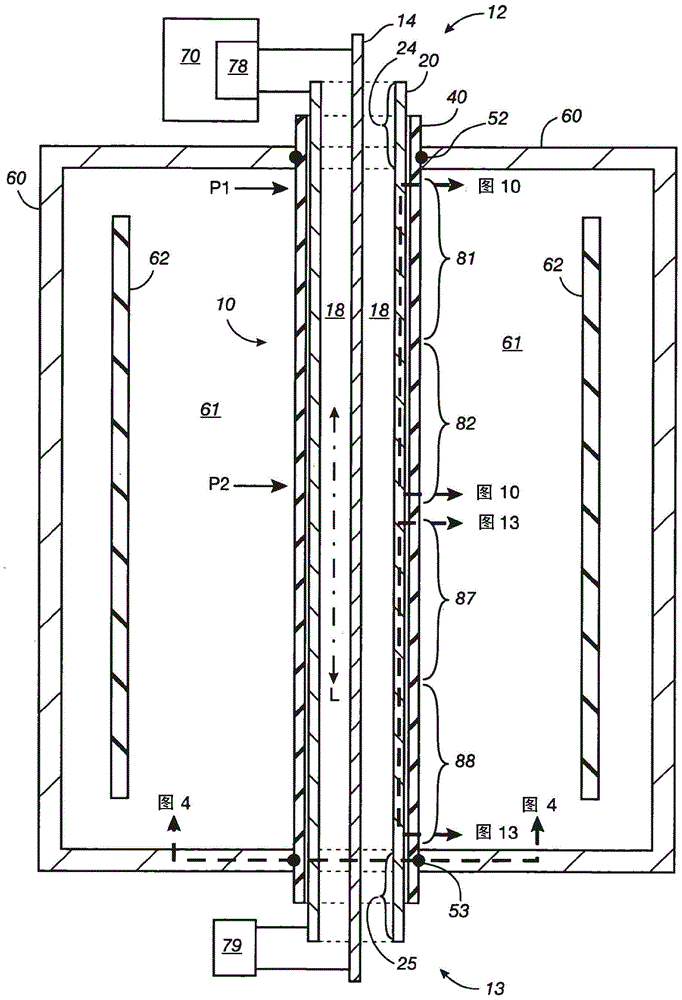
[0040] Figure 1 to Figure 22 Various embodiments of a two-conductor transmission line RF applicator 10 according to the first aspect or first embodiment of the invention are illustrated.

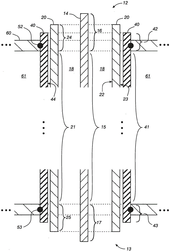
[0041]The RF applicator 10 includes an inner conductor 14 and an outer conductor 20 . The outer conductor 20 has a main portion 21 extending between a first end 24 and a second end 25 . Similarly, the inner conductor 14 has a main portion 15 extending between a first end 16 and a second end 17 . The main portion 15 of the inner conductor is located within and spaced apart from the main portion 21 of the outer conductor 20 .

[0042] We refer to the RF applicator 10 as having opposing first and second ends 12, 13 such that the first end 12 of the RF applicator is adjacent to the respective first ends 16, 24 of the inner and outer conductors, And the second end 13 of the RF applicator is adjacent...


PUM


Abstract

A transmission line RF applicator apparatus and method for coupling RF power to a plasma in a plasma chamber. The device consists of an inner conductor and one or two outer conductors. A substantial portion of each of the one or two outer conductors includes a plurality of holes extending between the inner and outer surfaces of the outer conductor.

Description

technical field [0001] The present invention generally relates to RF (radio frequency) applicator devices and methods for coupling RF power to plasma discharges in plasma chambers for the fabrication of electronic devices such as semiconductors, displays and solar cells. The present invention more particularly relates to an RF applicator comprising an inner conductor and one or two outer conductors, wherein each outer conductor has an aperture from which the RF applicator can radiate RF energy into a plasma chamber plasma in the chamber. Background technique [0002] Plasma chambers are commonly used to perform processes for manufacturing electronic devices such as semiconductors, displays and solar cells. Such plasma fabrication processes include chemical vapor deposition of semiconductor, conductor, or dielectric layers on the workpiece surface, or etching selected portions of the layers on the workpiece surface. [0003] A plasma is typically maintained by coupling RF p...

Claims


Application Information

Patent Timeline
Patent Type & Authority Patents(China)
IPC IPC(8): H05H1/46H01P3/10H01L21/3065
CPCH01J37/3211H01J37/3222H05H1/46H05H1/463
Inventor J·库德拉T·塔纳卡C·A·索伦森S·安瓦尔J·M·怀特R·I·欣德S-M·赵D·D·特鲁翁
Owner APPLIED MATERIALS INC
Why Eureka
Try Eureka