Polishing machine
A polishing machine and slider technology, applied in the polishing machine field, can solve the problem of inconsistent force applied by the polishing machine, and achieve the effect of improving the processing quality
- Summary
- Abstract
- Description
- Claims
- Application Information
AI Technical Summary
Problems solved by technology
Method used
Image

Examples
Embodiment Construction
[0028] The present invention will be described in further detail below in conjunction with the accompanying drawings and specific embodiments.
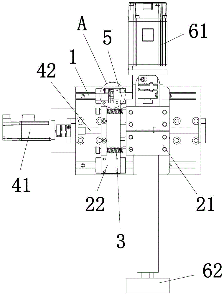
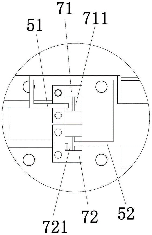
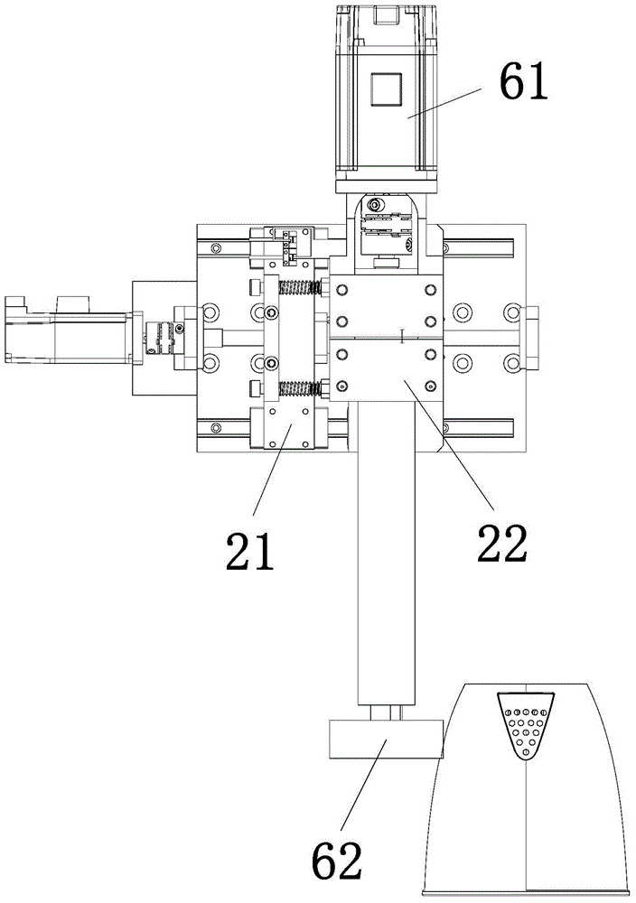
[0029] Such as figure 1 and 2 As shown, the polishing machine of the present invention includes a slide rail 1, a driving device and a controller; a first slide block 21 and a second slide block 22 that can move toward and away from each other are installed on the slide rail 1, the A telescopic spring connector 3 is connected between the first slider 21 and the second slider 22; the driving device is connected with the second slider 22, wherein the driving device includes a first motor 41 and a screw mandrel 42, The first motor 41 is connected with the screw rod 42 , and the screw rod 42 is connected with the second slider 22 . A force control sheet 5, a second motor 61 and a polishing wheel 62 are installed on the first slider 21, and the force control sheet 5 extends toward the second slider 22, and the first slider 22 is installe...
PUM
 Abstract
Description
Claims
Application Information
 - Generate Ideas
- Intellectual Property
- Life Sciences
- Materials
- Tech Scout
- Unparalleled Data Quality
- Higher Quality Content
- 60% Fewer Hallucinations
Browse by: Latest US Patents, China's latest patents, Technical Efficacy Thesaurus, Application Domain, Technology Topic, Popular Technical Reports.
© 2025 PatSnap. All rights reserved.Legal|Privacy policy|Modern Slavery Act Transparency Statement|Sitemap|About US| Contact US: help@patsnap.com