Method for producing an air guide for a suspension arm and suspension arm with an air guide

A technology of a guide device and a control arm, which is applied to the cantilever mounted on the pivot, the brake, the cooling brake, etc., can solve the problem of reduced rigidity, and achieve the effect of good rigidity characteristics, reasonable cost, and small processing overhead.

Inactive Publication Date: 2014-10-15
AUDI AG
View PDF8 Cites 6 Cited by
  • Summary
  • Abstract
  • Description
  • Claims
  • Application Information

AI Technical Summary

Problems solved by technology

The disadvantage is the reduced rigidity due to the profile shape of the opening

Method used


Image

  • Method for producing an air guide for a suspension arm and suspension arm with an air guide
  • Method for producing an air guide for a suspension arm and suspension arm with an air guide
  • Method for producing an air guide for a suspension arm and suspension arm with an air guide

Examples


Embodiment Construction

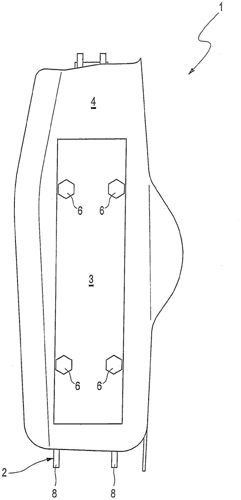
[0043] according to figure 1 , the flow guide device 1 has a reinforcing element 3 and a flow guide element 4 made of plastic connected to it. The stiffening element 3 has a higher rigidity than the flow guiding element 4 . The reinforcing element 3 can be fastened to the chassis control arm 2 by means of fasteners 6 and thereby reinforce the chassis control arm. The air guide element 3 is aerodynamically shaped in such a way that, when the chassis control arm 2 is installed in the wheel suspension of the motor vehicle, it improves the air flow in this area and protects the chassis control arm 2 from damage from stone impacts.

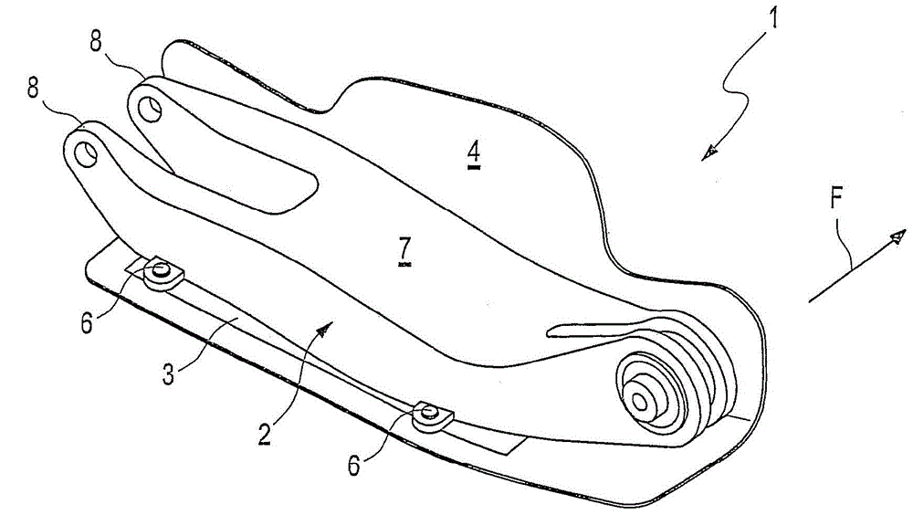
[0044] exist figure 2The chassis control arm 2 is shown in , comprising a base surface 7 and two side plates 8 protruding substantially at right angles from the base surface 7 . The lower end of the side plate 8 is bent relative to the horizontal, so that the fasteners 6 for arranging the reinforcement elements 3 of the air guide device 1 can be ac...


PUM


Abstract

The invention relates to a suspension arm 2 with an air guide 1, wherein the suspension arm 2 has in the installation position a downwardly open cross-sectional profile with a base surface 7 and at least two side webs 8 projecting from the base surface 7, and wherein the air guide 1 has a reinforcement element 3 to be arranged on the side webs 8 and an air guiding element 4 composed of a plastic material, and the invention further includes a method for producing an air guide 1 for a suspension arm 2.

Description

technical field [0001] The invention relates to a method for producing a deflector / air guide for a chassis control arm, comprising the steps of providing reinforcement elements for arrangement on the chassis control arm and using a deflector made of plastic Element / air guide element overmolding the reinforcing element, the invention also relates to a chassis control arm with a deflector, wherein the chassis control arm has a base surface and at least two side plates protruding from the base surface. , a cross-sectional profile that is open downwards in the installation position, wherein the flow guiding device can be arranged on the side plate. Background technique [0002] Air guides of this type are provided in vehicle construction on chassis control arms (also called transverse control arms or simply control arms) in order to thereby achieve a better underbody in the region of the wheel suspension flow around. The wheel suspension connects the wheel to the body and guid...

Claims


Application Information

Patent Timeline
Patent Type & Authority Applications(China)
IPC IPC(8): B60G7/00
CPCB60G7/001B60G2206/16B60G2206/014B62D35/02B60T5/00B62D37/02B60G2206/10F16D65/80B60G2204/4308B62D29/004Y02T10/88
Inventor A·奥廷格H-J·朗霍夫
Owner AUDI AG
Why Eureka
Try Eureka