
A kind of traction structure and traction construction method for vertical rotation construction of arch rib

A construction method and vertical technology, applied in the erection/assembly of bridges, bridges, buildings, etc., can solve the problems of cable tower breakage, waste of production costs, manpower and working hours for erection and dismantling, and save manpower and Material strength, the effect of improving balance and stability

Active Publication Date: 2016-05-11
CHINA CONSTR EIGHT ENG DIV CORP LTD
View PDF6 Cites 1 Cited by
  • Summary
  • Abstract
  • Description
  • Claims
  • Application Information

AI Technical Summary

Problems solved by technology

[0005] The requirements for the site and equipment are extremely high. Not only does it require a large site to build the buckle tower, the jack anchor structure, and the tension cable wind cable, but also after the construction is completed, heavy demolition and cleaning work must be carried out. Dismantling such a large buckle tower not only consumes manpower and working hours, but also causes huge waste of production costs
[0006] 2. The bottom of the buckle tower is fixedly connected to the bridge deck through the box girder structure. When the cable wind rope is used for traction and tension, the buckle tower has an outward bending moment, which is easy to cause the buckle tower to be broken. Pull off, causing serious engineering accidents

Method used


Image

  • A kind of traction structure and traction construction method for vertical rotation construction of arch rib
  • A kind of traction structure and traction construction method for vertical rotation construction of arch rib
  • A kind of traction structure and traction construction method for vertical rotation construction of arch rib

Examples


Embodiment Construction

[0035] The present invention will be further described in detail below in conjunction with the accompanying drawings and specific embodiments.

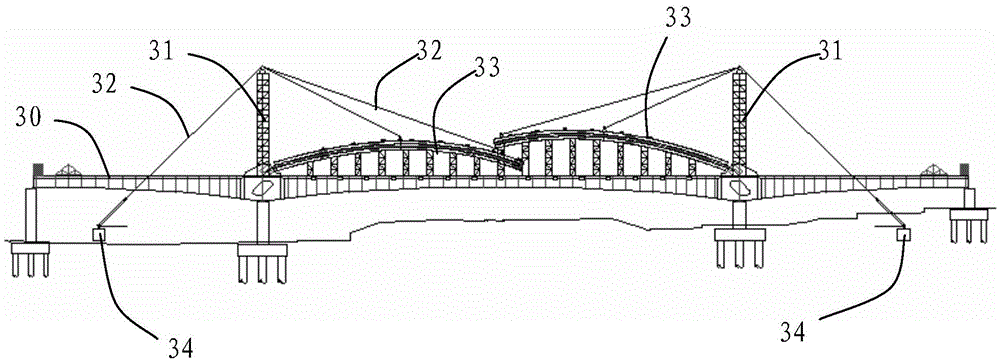
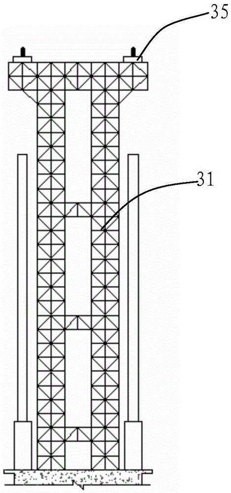
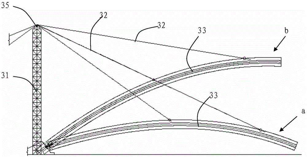
[0036] see first Figure 5 As shown, a traction structure for the vertical swivel construction of an arch rib according to the present invention is mainly composed of a column 11 , a lifting device 12 , a traction rope 13 and a cable wind rope 14 . Cooperate Figure 6As shown, the bottom of the column 11 is set on the structural foundation, the lifting device 12 is a jack, fixed on the top of the column 11, the arch rib 21 is arranged on the first side 111 of the column 11, and the end of the arch rib 21 close to the column 11 passes through A hinged seat 22 is hinged on the structural foundation to form a hinged end 151. The arch rib 21 is provided with a traction suspension point 152. The traction rope 13 is pulled between the traction suspension point 152 and the lifting device 12, and is provided by the lifting device 12. The ar...


PUM


Abstract

The invention discloses a traction structure for construction of a vertical rotating body of an arch rib and a traction construction method. The traction construction method includes the steps: arranging the bottom of an upright on a structure foundation, and mounting a lifting device at the top of the upright; mounting the arch rib on a first side of the upright, enabling a hinging end of the arch rib to be hinged on the structure foundation, and arranging a traction hanging point on the arch rib; arranging a traction rope between the traction hanging point and the lifting device in a pulled manner; arranging a cable-stayed rope on a second side of the upright in a pulled manner, and enabling a first end of the cable-stayed rope to be fixed at the top of the upright and a second end of the same to be fixed on the structure foundation; starting the lifting device to lift the arch rib to a designed position. The upright is utilized to replace a conventional buckle cable tower to set up a traction system like a steel wire rope and the cable-stayed rope, the lifting device is arranged at the top of the upright, the arch rib and the traction rope are arranged on the first side of the upright, and traction lifting is performed on the arch rib on the first side of the upright, so that the problem that the upright is damaged due to lateral torque caused to the upright in the process of traction is avoided, and balance stability of the upright is improved.

Description

technical field [0001] The invention relates to a bridge construction method, in particular to a traction structure and a traction construction method for vertical swivel construction of an arch rib. Background technique [0002] Existing long-span steel arch bridges are generally constructed using the cantilever buckle-hanging method or the swivel method. The cantilever buckle hanging method generally uses a cable crane to hoist the arch ribs for cantilever assembly, and the installed arch ribs are anchored on the cable buckle tower through the buckle cables; the swivel method is to divide the arch ring or the entire upper structure into two half arches, Then set up arch rib brackets on the formed bridge deck, assemble the half arches on the brackets, and turn the whole horizontally or vertically into place. The cantilever buckle hanging method is a mature construction method, but in the construction process, since the arch rib is a large cantilever structure supported by ...

Claims


Application Information

Patent Timeline
Patent Type & Authority Patents(China)
IPC IPC(8): E01D21/08
Inventor 马明磊孙同田王杰王桂玲王国欣
Owner CHINA CONSTR EIGHT ENG DIV CORP LTD
Learn More