A hydraulic fracturing microseismic monitoring device and monitoring method

A technology of microseismic monitoring and hydraulic fracturing, which is applied in the directions of surveying, earthwork drilling, and mining fluids, etc. It can solve the problems affecting the normal monitoring process of the microseismic monitoring system, the difficulty of installing microseismic monitoring sensors, and the inconvenience of sensor installation position adjustment, etc., to achieve The monitoring effect is good, the microseismic monitoring accuracy is guaranteed, and the use effect is good.

Inactive Publication Date: 2017-03-29
SHANXI LUAN ENVIRONMENTAL ENERGY DEV +1
View PDF5 Cites 0 Cited by
  • Summary
  • Abstract
  • Description
  • Claims
  • Application Information

AI Technical Summary

Problems solved by technology

[0005] However, since the microseismic monitoring sensors used in the existing microseismic monitoring system are all installed underground, the following problems exist in the actual use process: first, the microseismic monitoring sensors are difficult to install, the installation method is complicated, time-consuming and laborious, and the installation cost is high; 1. The installation quality is difficult to guarantee, and the installed sensors are easy to fall off, which affects the normal monitoring process of the microseismic monitoring system; third, the flexibility is poor. Once the sensor is installed, it is difficult to adjust the installation position. The installation position is inconvenient to adjust and other problems; Fourth, the microseismic monitoring sensor is located below the ground, and a long-distance signal transmission system is required for signal transmission, and the signal transmission attenuation is large, thus affecting the monitoring accuracy

Method used


Image

  • A hydraulic fracturing microseismic monitoring device and monitoring method
  • A hydraulic fracturing microseismic monitoring device and monitoring method
  • A hydraulic fracturing microseismic monitoring device and monitoring method

Examples


Embodiment Construction

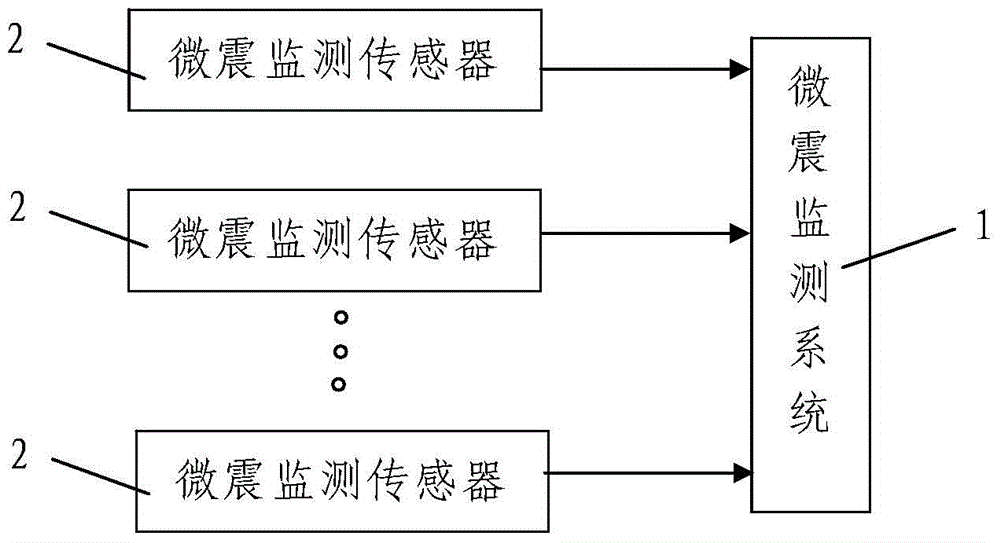
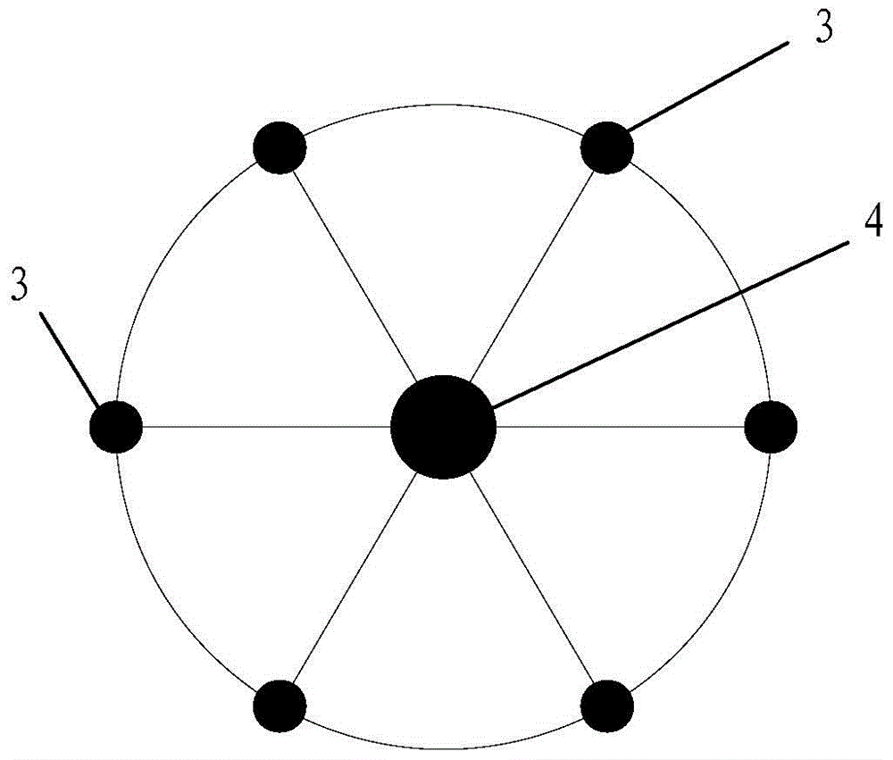
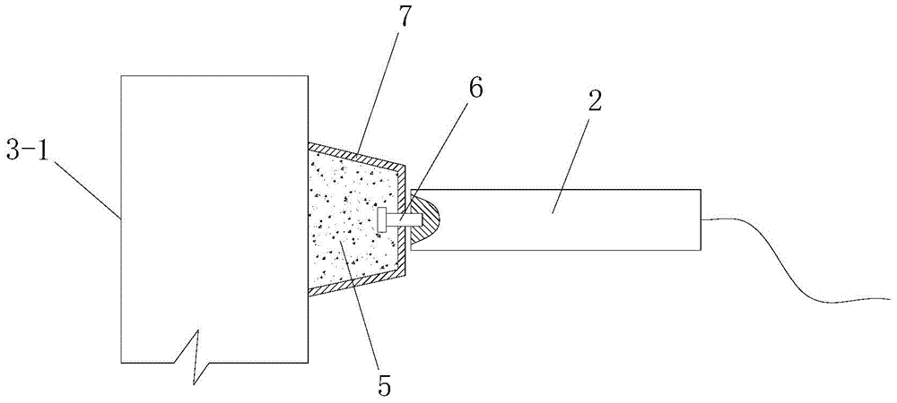
[0047] Such as figure 1 The shown microseismic monitoring device for hydraulic fracturing includes a plurality of microseismic monitoring sensors 2 and a microseismic monitoring system 1 connected to the plurality of microseismic monitoring sensors 2 . A plurality of the microseismic monitoring sensors 2 are respectively arranged on the wellbore installed in the plurality of monitoring wells 3, and the plurality of monitoring wells 3 are arranged on the outside of the fracturing hole for hydraulic fracturing in the current state. The distance between the monitoring well 3 and the fracturing hole is less than 300m. The shafts installed in each of the monitoring wells 3 are composed of a ground exposed section 3-1 above the ground and an underground buried section 3-2 below the ground. The microseismic monitoring sensor 2 is arranged on the outer wall of the ground exposed section 3-1, and the inner end of the microseismic monitoring sensor 2 is equipped with a connecting piece...


PUM


Abstract

The invention discloses a hydrofracture and micro-seismic monitoring device and a hydrofracture and micro-seismic monitoring method. The monitoring device comprises a plurality of micro-seismic monitoring sensors and a micro-seismic monitoring system, wherein the plurality of micro-seismic monitoring sensors are respectively distributed on shafts installed in a plurality of monitoring wells, and each shaft is composed of a ground exposed section and an underground embedded section; the micro-seismic monitoring sensors are distributed on the outer side walls of the ground exposed sections, the inner ends of the micro-seismic monitoring sensors are provided with connectors, and the outer ends of the connectors are tightly adhered to the outer side walls of the ground exposed sections and fixed to the ground exposed sections through anchoring agents; the monitoring method comprises the steps of: 1, selection of the monitoring wells; 2, installation of the micro-seismic monitoring sensors; 3, wiring of the micro-seismic monitoring sensors; 4, monitoring of hydrofracture and micro-seism. The monitoring device is reasonable in design, convenient to implement, good in use effect and high in monitoring accuracy, and can effectively solve the problems that the micro-seismic monitoring sensor is complex in installation method, high in installation cost, not strong in flexibility, large in signal transmission attenuation, easy to drop, poor in monitoring effect and the like.

Description

technical field [0001] The invention belongs to the technical field of microseismic monitoring, and in particular relates to a hydraulic fracturing microseismic monitoring device and a monitoring method. Background technique [0002] Hydraulic fracturing technology was first used in the development of oil and gas fields to increase the production of oil and gas wells. Hydraulic fracturing is an oil and gas well stimulation measure with wide application prospects. Hydraulic fracturing uses high-pressure pumps on the surface and squeezes fracturing fluid with high viscosity into the oil layer through the wellbore. When the absorption capacity is high, a very high pressure is formed on the oil layer at the bottom of the well. When this pressure exceeds the fracture pressure of the rock in the oil layer near the bottom of the well, the oil layer will be pushed open and cracks will be generated. In the 1960s, the former Soviet Union introduced this technology into coal mines as ...

Claims


Application Information

Patent Timeline
Patent Type & Authority Patents(China)
IPC IPC(8): E21B47/12E21B43/26
Inventor 刘保金张天军冯培文刘超冯绪兴王宁郝少伟宋建利李会玲秦安国宋爽王韶伟孙盛涛吴垚垒范宏宇
Owner SHANXI LUAN ENVIRONMENTAL ENERGY DEV
Why Eureka
Try Eureka