
Improved vane hydraulic pump and motor

A hydraulic motor and vane type technology, applied in the field of hydraulic machinery, can solve the problems of fluid leakage, inability to further improve the performance and durability of hydraulic machinery, low volumetric efficiency, etc., and achieve the effects of reasonable pressure, simple structure and improved volumetric efficiency.

Active Publication Date: 2017-03-01
胡凯
View PDF7 Cites 0 Cited by
  • Summary
  • Abstract
  • Description
  • Claims
  • Application Information

AI Technical Summary

Problems solved by technology

[0006] The purpose of the present invention is to solve the problems of fluid leakage, low volumetric efficiency, and the performance and durability of the hydraulic machine cannot be further improved due to the influence of the liquid medium in the prior art, and to provide a simple structure, manufacturing Convenient, can effectively solve the problem of fluid leakage, significantly improve volumetric efficiency, and can be widely used in improved vane hydraulic pumps and motors of vane hydraulic machinery under various medium conditions

Method used


Image

  • Improved vane hydraulic pump and motor
  • Improved vane hydraulic pump and motor
  • Improved vane hydraulic pump and motor

Examples


Embodiment 1

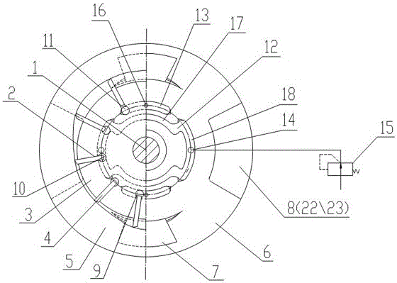
[0026] exist figure 1 In the shown embodiment, the improved vane hydraulic pump and motor include a rotor 3 that rotates on the transmission shaft 1 and is provided with several radial slots 2, vanes 4 that slide along the radial slots 2, and are arranged outside the rotor 3. The stator 5 cooperating with the rotor 3, the side plate 6 installed at both ends of the rotor 3, the side plate 6 is provided with a high-pressure chamber 7 and a low-pressure chamber 8, the corresponding pump is an inflow low-pressure chamber 22, and the corresponding motor is an outflow low-pressure chamber 23 , this embodiment is a hydraulic motor. The top of the blade 4 is in contact with the inner surface of the stator 5, and the control chamber 9 is formed between the blade 4 and the radial groove 2 of the rotor. During the rotation of the rotor 3, the blade 4 slides in and out along the radial groove 2 to form a volume change of the control chamber. At least one volume expansion section control ...

Embodiment 2

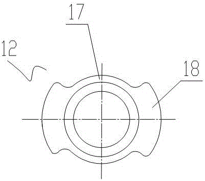
[0028] exist Figure 4 In the illustrated embodiment, the improved vane hydraulic pump and motor are basically the same as in Embodiment 1, except that the leakage recovery chamber 12 includes two groups arranged symmetrically about the same axis, and each group consists of a waist-shaped The groove 18 is connected with two recovery grooves 17 arranged at both ends of the waist-shaped groove 18, and the two groups of leakage recovery chambers 12 are separated.

Embodiment 3

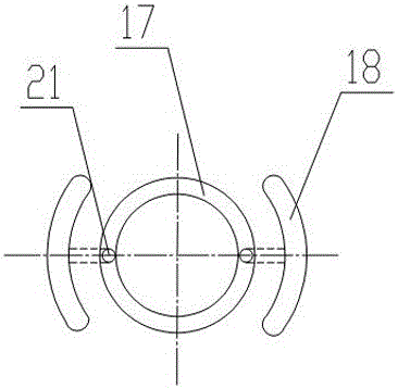
[0030] exist Figure 5 In the shown embodiment, the improved vane hydraulic pump and motor are basically the same as Embodiment 1, the difference is that: the leakage recovery chamber 12 includes two groups arranged symmetrically with the same axis, and each group consists of an arc The recovery tank 17 is connected to a waist-shaped tank 18, and the two groups of leakage recovery chambers 12 are separated.


PUM


Abstract

The invention discloses an improved blade type hydraulic pump and a motor. The improved blade type hydraulic pump and the motor comprise a rotor rotated on a transmission shaft and provided with a plurality of radial grooves, blades slipped along the radial grooves, a stator arranged outside the rotor and cooperating with the rotor, and side plates mounted at the two ends of the rotor. A high-pressure cavity and a low-pressure cavity are formed in the side plates; the top ends of the blades are contacted with the inner surface of the stator; control cavities are formed between the bottoms of the blades and the radial grooves of the rotor; in the each cycle of rotation of the rotor, the blades are slipped inside and outside along the radial grooves to cause the volume variation of lower cavities of the blades so as to form at least one volume expansion section control cavity and at least one volume shrinkage section control cavity; a leakage recovery cavity and a leakage discharge cavity are formed in the side plates; the leakage recovery cavity is communicated with the volume expansion section control cavity, and is communicated with the high-pressure cavity via a flow passage through a control valve; and the leakage discharge cavity is communicated with the volume shrinkage section control cavity, and is communicated with the high-pressure cavity through a small hole. The leakage recovery structure provided improves the volume efficiency and the performance and durability of hydraulic machines.

Description

technical field [0001] The invention relates to the technical field of hydraulic machinery, in particular to an improved vane type hydraulic machine, especially an improved vane type hydraulic pump and motor. Background technique [0002] Vane hydraulic pumps or hydraulic motors are usually composed of rotors, vanes, stators, side plates, etc. There is a certain gap between the rotor and the end faces of the side plates. Under high fluid pressure, the fluid will pass through the gap to cause fluid leakage, thus Reduces the volumetric efficiency of hydraulic machinery, resulting in wasted energy. [0003] Chinese patent literature (announcement date: June 8, 1994, announcement number: CN 2168098Y) discloses a cam rotor vane pump with a hydraulically floating side plate. Compensate the axial gap caused by wear between the rotor, the pressure side plate and the oil distribution plate to maintain a high volumetric efficiency; the flow channel in the pump body is clear, which ma...

Claims


Application Information

Patent Timeline
Patent Type & Authority Patents(China)
IPC IPC(8): F04C2/344F04C15/00
Inventor 胡凯
Owner 胡凯
Learn More