Method for designing linearity of mounting surface for rolling linear guide of precision machine tool

A linear guide rail and precision machine tool technology, applied in computing, special data processing applications, instruments, etc., can solve problems such as demanding parts accuracy, and achieve the effect of shortening the product development cycle

Active Publication Date: 2014-10-15
XI AN JIAOTONG UNIV
View PDF1 Cites 8 Cited by
  • Summary
  • Abstract
  • Description
  • Claims
  • Application Information

AI Technical Summary

Problems solved by technology

The extreme value method needs to consider the worst case in the assembly process, which will result in very strict requirements on the a

Method used


Image

  • Method for designing linearity of mounting surface for rolling linear guide of precision machine tool
  • Method for designing linearity of mounting surface for rolling linear guide of precision machine tool
  • Method for designing linearity of mounting surface for rolling linear guide of precision machine tool

Examples


Embodiment Construction

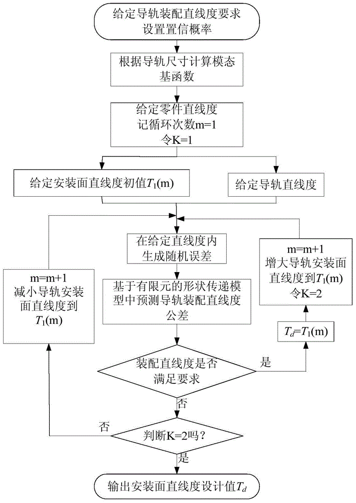
[0025] Such as figure 1 As shown, the design method of the straightness tolerance of the rolling linear guide rail mounting surface of the precision machine tool of the present invention comprises the following steps:

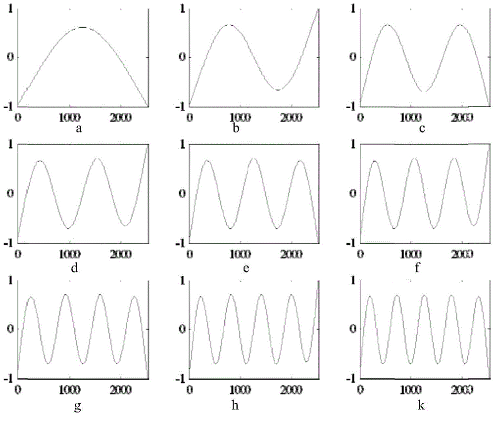
[0026] 1) Since it is more complicated to obtain the modal basis function by the analytical method, the system can be discretized, and the modal vector can be obtained conveniently by using the finite element software, and then the normalization principle ||Y can be used i || ∞ =1, the uniquely determined modal basis function is obtained. According to the size of the guide rail, the modal basis function Y of the assembly characteristic surface is obtained by using ANSYS finite element software;

[0027] The shape error of the guide rail is expressed by the modal basis function and the modal coefficient, and the mean value of the modal coefficient μ of the guide rail is obtained by using the mapping relationship between the shape error of the guide rail and th...


PUM


Abstract

A method for designing linearity of a mounting surface for a rolling linear guide of a precision machine tool includes the steps of first, expressing a form error of a fitting characteristic surface by means of a modal base function based method, and generating a random error sample within a given linearity tolerance; second, establishing a finite element based form error propagation model according to the generated random error sample by means of finite element software ANSYS, acquiring a fitting error of the rolling linear guide by means of finite element analysis, using the Monte-Carlo method to input all random errors generated within a given tolerance zone, into the finite element based form error propagation model and to calculate the random errors so that a post-fitting linearity tolerance is obtained, and establishing a guide fitting tolerance analysis model; and third, on the basis of the guide fitting tolerance analysis model, designing the linearity of the mounting surface for the rolling linear guide according to the concept of cyclic search. The method has the advantages that dependence on experiences is reduced, reliable theoretical guidance is provided for the design of the linearity of the guide mounting surface, product development time can be shortened, cost can be reduced, and economic benefit can be increased.

Description

technical field [0001] The invention belongs to the field of tolerance design, and in particular relates to a method for designing the straightness of a rolling linear guide rail mounting surface of a precision machine tool. Background technique [0002] The assembly accuracy of the guide rail of the machine tool directly affects the accuracy of the feed system of the machine tool, which in turn affects the accuracy performance of the machine tool, while the assembly accuracy of the guide rail is mainly affected by the straightness of the guide rail installation surface. How to reasonably design the straightness of the mounting surface to ensure the assembly accuracy of the guide rail is an important proposition. In the design of the straightness of the mounting surface of the rolling linear guide rail of precision machine tools, the designers mainly rely on the design manual and previous design experience. In the development of new products, they have to adopt the method of...

Claims


Application Information

Patent Timeline
IPC IPC(8): G06F17/50G06F19/00
Inventor 刘志刚洪军武晓攀郭俊康李逸群
Owner XI AN JIAOTONG UNIV
Why Eureka
Try Eureka