Bottle-making machine and production process for manufacturing extra-large glass bottles

A production process and glass bottle technology, which is applied in glass production, glass blowing molding machines, special transmission machinery for glass blowing machines, etc. The effect of maintaining strength, less mold wear, and uniform bottle wall thickness

Active Publication Date: 2014-10-22
SHANDONG JIAFENG GLASS MACHINERY
View PDF4 Cites 10 Cited by
  • Summary
  • Abstract
  • Description
  • Claims
  • Application Information

AI Technical Summary

Problems solved by technology

Due to the large body of the bottle, manual intervention such as turning over and handling will inevitably cause burns, which poses a threat to the personal safety of workers
In addition, due to the large size and weight of the bottle, the bottle body will also break or deform due to gravity when it is turned over. It can be seen that there are many difficulties in the production of large bottles

Method used


Image

  • Bottle-making machine and production process for manufacturing extra-large glass bottles
  • Bottle-making machine and production process for manufacturing extra-large glass bottles
  • Bottle-making machine and production process for manufacturing extra-large glass bottles

Examples


Embodiment 1

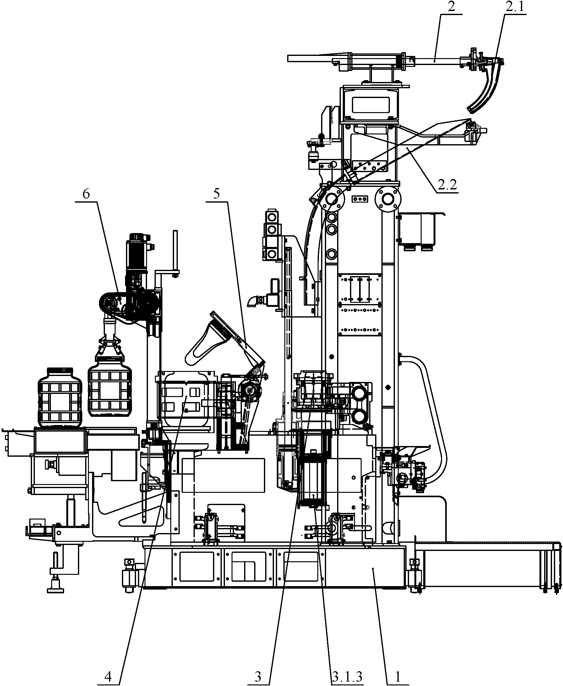
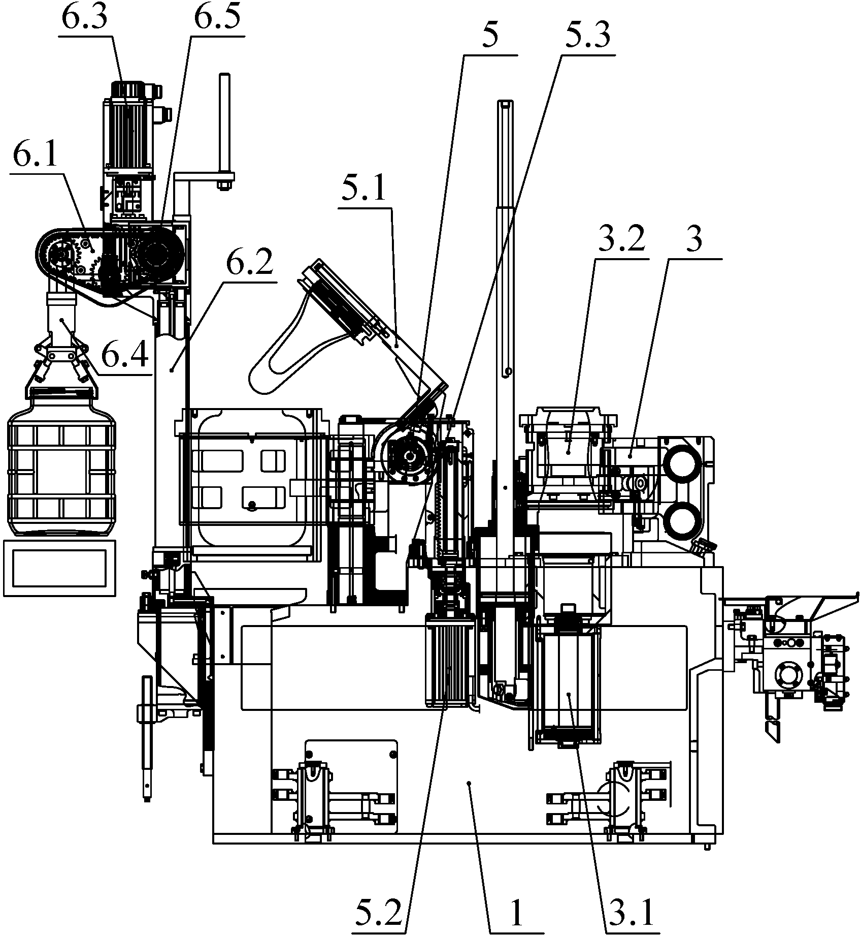
[0052] A bottle making machine for making extra large glass bottles such as figure 1 As shown, it includes a frame 1 and a preliminary mold forming mechanism 3 , a forming mold forming mechanism 4 and a turning device 5 all installed on the frame 1 .

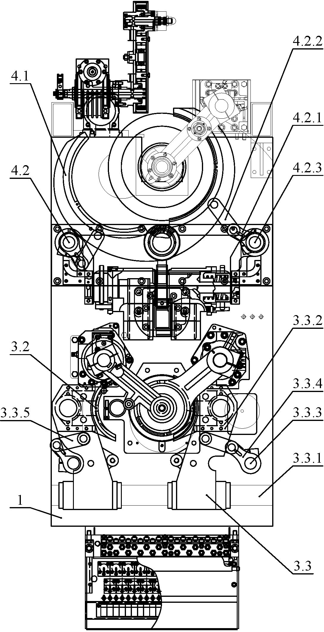
[0053] Such as Figure 4 As shown, the blank mold forming mechanism 3 includes a stamping device 3.1, a blank mold 3.2 and a parallel switch mechanism 3.3. The stamping device 3.1 is installed on the frame 1, and the parallel switch mechanism 3.3 includes a horizontal guide shaft 3.3.1 installed on the frame 1, a parallel clamp arm 3.3.2 set on the horizontal guide shaft 3.3.1, and a vertical set on the The first spline shaft 3.3.3, the first rocker arm 3.3.4, the first connecting rod 3.3.5 and the first switch cylinder on both sides of the frame 1. One end of the first connecting rod 3.3.5 is hinged with the parallel tong arm 3.3.2, and the other end is hinged with the first rocker arm 3.3.4. The first rocking arm 3.3.4 is c...

Embodiment 2

[0076] The difference from Example 1 is that the preliminary molding stage in this example uses the "blowing-blowing" method to obtain preforms. Such as Figure 9 As shown, the preliminary mold forming mechanism includes an air blowing device 3.5, and the blowing device is positioned under the preliminary mold. The blowing device includes a core 3.5.1, a buckle 3.5.2, a core joint 3.5.3, a core spring 3.5.5 and a blowing cylinder 3.5.6. The sleeve 3.5.4 is fitted around the core, and the core and the sleeve can slide relative to each other in the radial direction. The core and the core joint are connected by a buckle, and the lower end of the core joint is connected with the blowing cylinder. The core joint is connected with the cylinder block of the blowing cylinder by a core spring. A blowing channel is provided inside the core and the core joint, the top of the blowing channel passes through the side wall of the core and communicates with the outside world, and the botto...


PUM


Abstract

The invention relates to a bottle-making machine and a production process for manufacturing extra-large glass bottles, and belongs to the field of bottle-making machine equipment. The bottle-making machine comprises a rack, and a primary mold forming mechanism, a formed mold forming mechanism and a turnover mechanism which are arranged on the rack, wherein the primary mold forming mechanism comprises a stamping device, a primary mold and a parallel switching mechanism; the stamping device is mounted on the rack; the parallel switching mechanism comprises a horizontal guide shaft mounted on the rack, a clamp arm which sleeves on the horizontal guide shaft, and a first spline shaft, a first rocker arm, a first connecting rod and a first switching cylinder which vertically sleeve at two sides of the rack; one end of the first connecting rod is hinged with the clamp arm while the other end of the first connecting rod is hinged with the first rocker arm; the first rocker arm is connected with the first switching cylinder through the first spline shaft; the primary mold is mounted on the clamp arm. The bottle-making machine has the beneficial effects that the extra-large glass bottles are produced in a manner of automatic mechanized production for replacing manual production, so that the yield of the extra-large glass bottles is increased and the quality of the extra-large glass bottles is improved.

Description

technical field [0001] The invention belongs to the field of bottle-making machine equipment, and in particular relates to a bottle-making machine and a production process for making extra-large glass bottles. Background technique [0002] In the glass bottle production industry, the bottle making machine adopts multi-drop forming technology to increase the output of a single machine. After decades of development, it has been promoted from single-drop bottle making to six-drop bottle making, such as the invention patent with application number 201010253079.0 (a six-drop determinant bottle making machine and its production process), which can save energy consumption in a single machine Under the same premise, the output of glass bottles is several times that of traditional bottle making machines, and the production cost is greatly reduced. The corresponding production process has also appeared "blow-blow method" and "press-blow method"; The production process of initial mol...

Claims


Application Information

Patent Timeline
Patent Type & Authority Applications(China)
IPC IPC(8): C03B9/193C03B9/40
CPCY02P40/57
Inventor 景传舜王承尧杨自皆于书杰景光成杨鹏马军
Owner SHANDONG JIAFENG GLASS MACHINERY
Why Eureka
Try Eureka