Low-permeability rock-fill material concrete panel rock-fill dam

A concrete face, low permeability technology, applied in the direction of dams, barrages, barrages, etc., can solve the problems affecting the stability and safety of the dam body seepage, low permeability coefficient, etc., to ensure the safety of the dam body, improve the seepage stability, Ease of application

Inactive Publication Date: 2014-10-22
POWERCHINA XIBEI ENG +1
View PDF3 Cites 26 Cited by
  • Summary
  • Abstract
  • Description
  • Claims
  • Application Information

AI Technical Summary

Problems solved by technology

[0004] The purpose of the present invention is to overcome the problem in the prior art that the rockfill material permeability coefficient of concrete face rockfill dams is low, which affects the stability and safety of the dam body seepage

Method used


Image

  • Low-permeability rock-fill material concrete panel rock-fill dam
  • Low-permeability rock-fill material concrete panel rock-fill dam

Examples


Embodiment 1

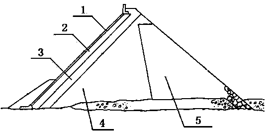
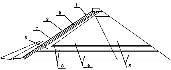
[0018] In order to overcome the problem in the prior art that the permeability coefficient of the rockfill material of the concrete face rockfill dam is low, which affects the stability and safety of the dam body seepage, this embodiment provides a method such as figure 2 The low-permeability rockfill concrete face rockfill dam shown includes concrete face 1, cushion layer area 2, transition area 3, upstream main rockfill area 4 and downstream secondary rockfill area 5, which are arranged in sequence from upstream to downstream. Between the downstream side of the above-mentioned transition zone 3 and the upstream side of the upstream main rockfill area 4, an "L"-shaped drainage area 6 is arranged, and the horizontal part of the drainage area 6 crosses the upstream main rockfill area 4 and the downstream The bottom of the secondary rockfill area 5, and horizontally divides the upstream main rockfill area 4 and the downstream secondary rockfill area 5 into upper and lower parts,...

Embodiment 2

[0021] On the basis of Example 1, according to the engineering practice, the slope ratios of the concrete panel 1, the cushion area 2, the transition area 3, and the filter area-7 are the same, all of which are 1:m, and the value range of m is 1.3 to 1.6; the partition slope between the vertical part of the drainage area 6 and the upstream main rockfill area 4 is 1: s, and the value range of s is 1.4 to 1.7; the horizontal part of the drainage area 6 Set between the highest water level and the lowest water level in the downstream; the partition slope of the upstream main rockfill area 4 and the downstream secondary rockfill area 5 is 1:t, and the value range of t is 0 to 1.35, which is determined according to the actual project. Generally take 0.2; the selection of the above parameters must meet the requirements of the "Code for Design of Concrete Face Rockfill Dams" (DL / T5016-2011, SL228-98).

[0022] The concrete face 1 of this embodiment is used as an anti-seepage structure...


PUM


Abstract

The invention provides a low-permeability rock-fill material concrete panel rock-fill dam. The low-permeability rock-fill material concrete panel rock-fill dam comprises a concrete panel, a cushion area, a transition area, an upstream main rock-fill area and a downstream secondary rock-fill area which are formed in sequence from upstream to downstream; an L-shaped draining area is formed between the downstream side of the transition area and the upstream side of the upstream main rock-fill dam area; the horizontal portion of the draining area transversely passes through the bottoms of the upstream main rock-fill area and the downstream secondary rock-fill area; the upstream main rock-fill area and the downstream main rock-fill area are horizontally partitioned into an upper portion and a lower portion; a reverse filtering area I is formed between the downstream side of the transition area and the vertical portion of the draining area; a reverse filtering area II is formed between the horizontal portions of the upstream main rock-fill area as well as the draining area and the horizontal portions of the downstream secondary rock-fill area and the draining area. The reverse filtering area I, the reverse filtering area II and the draining area are formed on the basis of the conventional concrete panel rock-fill damp structure, thereby improving the permeating stability and the safety of a dam body. A rock-fill material is taken from local resources, thereby reducing the engineering building cost, and facilitating construction.

Description

technical field [0001] The invention belongs to the technical field of water conservancy engineering, and in particular relates to a low-permeability rockfill concrete face rockfill dam. Background technique [0002] At present, concrete face rockfill dams are basically concrete face rockfill dams. Because of their low cost and short construction period, concrete face rockfill dams have been vigorously developed. Such as figure 1 As shown, the concrete face rockfill dam is mainly composed of rockfill body and anti-seepage system, namely: concrete face, plinth, cushion area, transition area, upstream main rockfill area, and downstream secondary rockfill area. [0003] In the design and construction of concrete face rockfill dams, the seepage stability of the dam body is an important consideration, and the safety of face face dams and pivots are all closely related to this, so the dam body should No osmotic deformation occurs. In concrete face rockfill dams, low-permeabilit...

Claims


Application Information

Patent Timeline
Patent Type & Authority Applications(China)
IPC IPC(8): E02B7/06
Inventor 蔡新合白俊光王君利魏坚政陈念水王康柱李锋
Owner POWERCHINA XIBEI ENG
Why Eureka
Try Eureka