A Clock Control Circuit And Method

A clock control and circuit technology, applied in program control design, electrical digital data processing, signal generation/distribution, etc., can solve problems such as difficulty in implementing large processors

Inactive Publication Date: 2014-10-22
NXP BV
View PDF4 Cites 0 Cited by
  • Summary
  • Abstract
  • Description
  • Claims
  • Application Information

AI Technical Summary

Problems solved by technology

[0015] Traditionally, error detection and determination should be completed within one or half a clock cycle, which is difficult to achieve for large processors, and the above-mentioned methods fail to solve this problem

Method used


Image

  • A Clock Control Circuit And Method
  • A Clock Control Circuit And Method
  • A Clock Control Circuit And Method

Examples


Embodiment Construction

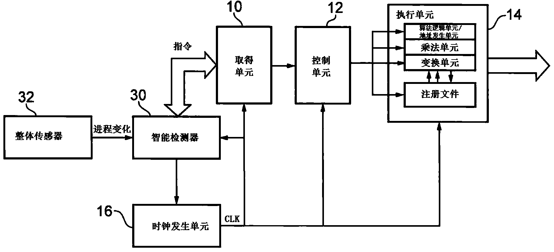
[0048] The present invention provides a clock control circuit that can be added to any on-the-fly processor to solve timing problems due to variations in process output and environmental conditions. Detect critical instructions (executed as critical paths) during environmental detection (such as process, temperature, and voltage). This information is used to control cycle stealing.

[0049] The present invention thus provides an architecture that is tolerant to variation to provide better than worst-case CPU designs. The present invention uses an intelligent error predictor, which is based on critical instructions. An intelligent in-transit stall unit is used to preserve the in-transit context and allow the correct execution of critical orders. If a critical instruction is executed, there will only be a penalty of one clock cycle.

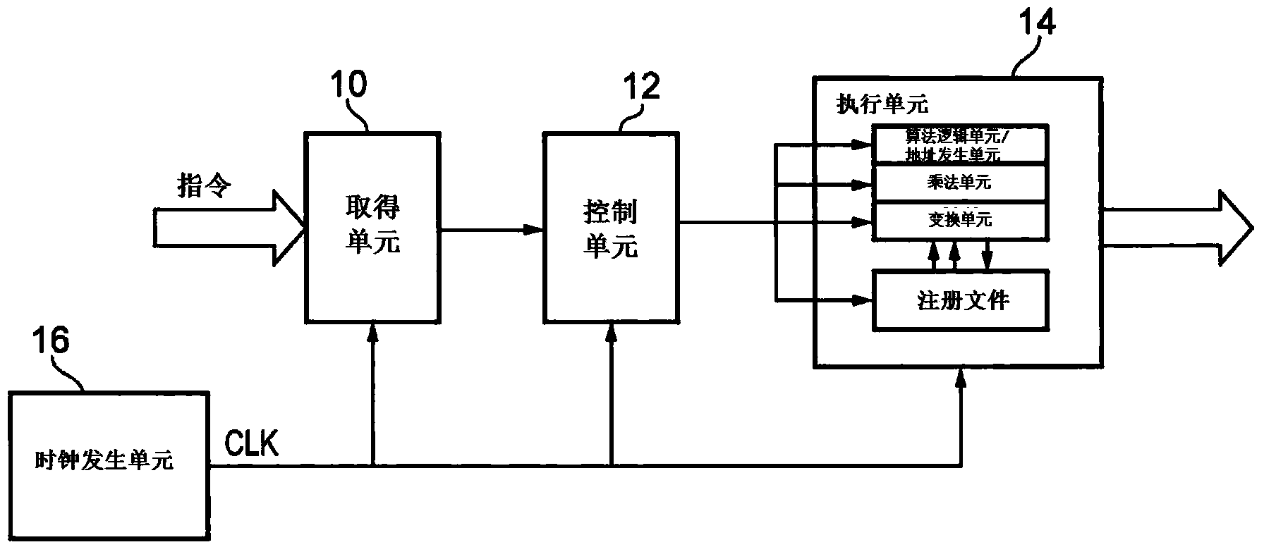
[0050] figure 2 Shown is a block diagram of a general-purpose processor into which the system of the present invention can be incorporated. ...


PUM


Abstract

This invention provides a clock control circuit, which can be added to any pipeline-processor to solve timing problems arising from variations due to process outcome and environmental conditions. Critical instructions are detected (instructions that exercise critical paths) in conjunction with environmental sensing (such as process, temperature and voltage). This information is used to control cycle stealing.

Description

technical field [0001] The present invention relates to the control of clock signals used by processors and, in particular, to selectively performing cycle stealing when needed. Background technique [0002] Design and manufacturing techniques have been used to reduce transistor size so that more and more transistors can be integrated on a single integrated circuit (IC), such as a system-on-chip (SoC). The evolution of technology also introduces significant challenges, such as high defect rates and device parameter variations. This change changes the propagation delay of the CMOS circuit, which in turn leads to the failure of the function of the IC. [0003] Traditional SoC design approaches meet timing requirements by considering "worst case" (WC) operating conditions, resulting in lower maximum operating frequencies and increased area and power overhead. [0004] Another "typical value" design method provides a better balance between area and performance and power consum...

Claims


Application Information

Patent Timeline
Patent Type & Authority Applications(China)
IPC IPC(8): G06F17/50
CPCG06F1/04G06F1/08G06F9/3869G06F11/00G06F11/004G06F11/3024G06F11/3058G06F1/06G06F9/38
Inventor 罕默德·费特米伦泽·I·M·P·迈耶吉亚斯·阿尔-卡迪苏兰达拉·冈都简·胡格布鲁格
Owner NXP BV
Why Eureka
Try Eureka