
Surgical clip and device for applying the clip

A technology of surgery and clamps, which is applied in the direction of surgery, wound clips, medical science, etc., and can solve the problems of partial or complete function loss and insufficient stability of clamps.

Inactive Publication Date: 2014-10-22
A·洪内费尔德 +2
View PDF7 Cites 3 Cited by
  • Summary
  • Abstract
  • Description
  • Claims
  • Application Information

AI Technical Summary

Problems solved by technology

Depending on the tissue resistance at a particular point and the clamping pressure applied, due to insufficient stability of the holding pins of the clamp, the clamping bars move away from each other in a V-shape and can thus result in partial or complete loss of function of the clamp. Excluded

Method used


Image

  • Surgical clip and device for applying the clip
  • Surgical clip and device for applying the clip
  • Surgical clip and device for applying the clip

Examples


Embodiment Construction

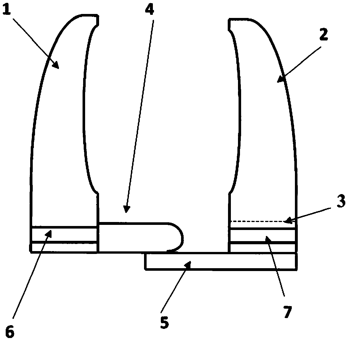
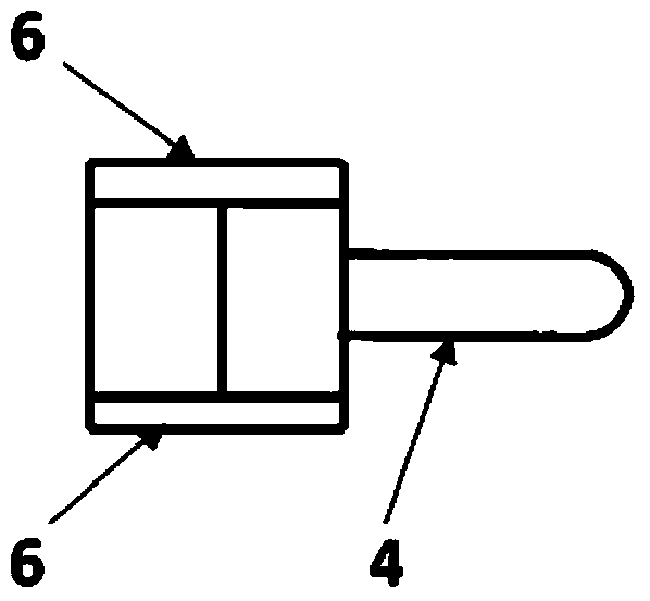
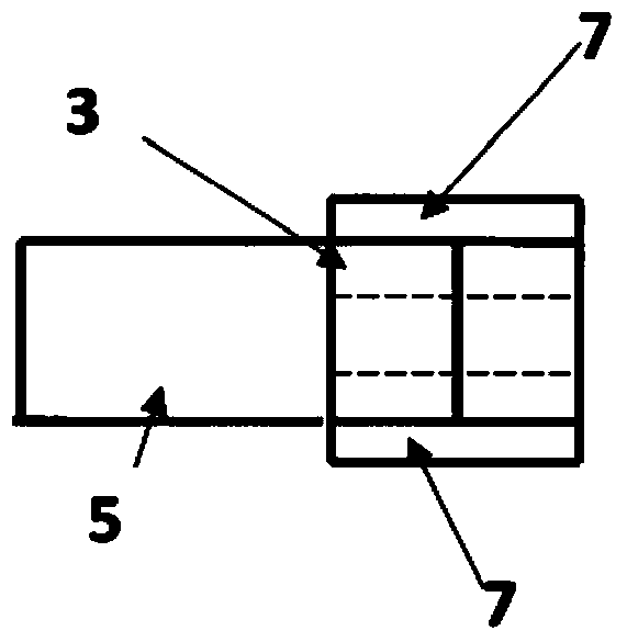
[0070] Such as figure 1 , Figure 1a , Figure 1b As shown, the clamp according to the invention consists of a first clamping bar 1 and a second clamping bar 2, which correspond to each other, the clamping surfaces of which are configured as concave and, if necessary, also have rough, corrugated or uneven surfaces. The clamping bars 1 , 2 can also have clamping surfaces which are configured as flat. The shoulders 6 and 7 are provided at the base of the clamping bars 1, 2, made of a known type of absorbable material; , 2 are guided laterally by means of these shoulders into matching slots 13, 22 of the cassette 11 for their application.

[0071] Essential to the invention is the handle 5 provided at the base of the second clamping bar 2 , which preferably fills the width of the base 12 of the cassette 11 . The first clamping rod 1 with the retaining pin 4 is positioned at the distal end of the cassette 11 (not shown) by pressure clamping. In order to clamp the tissue, the...


PUM


Abstract

The invention relates to a surgical clip for minimally invasive surgery and to a device for clamping organic tissue, consisting of a first clamping bar corresponding with a second clamping bar, wherein the first clamping bar and the second clamping bar each have, at both sides on their base, shoulders for guiding them into a cartridge, and one clamping bar has a continuous retaining bore into which, in order to clamp the organic tissue, a retaining pin provided on the other clamping bar engages with a force fit and form fit, the first clamping bar (1) is mounted by means of clamp pressing in a cartridge (11), and the second clamping bar (2) with the continuous retaining bore (3) has, at its lower end, an arm (5) which, upon joining to the first clamping bar (1), slides with a form fit under the shorter first clamping bar (1) with the retaining pin (4), thus clamping the organic tissue, or the first clamping bar (1) with the retaining pin (4) at its lower end has the arm (5) which, upon joining to the second clamping bar (2), slides with a form fit under the shorter second clamping bar (2) with the retaining bore (3), thus clamping the organic tissue, or the second clamping bar (2), which has both the retaining pin (4) and also the arm (5), upon joining to the first clamping bar slides with a form fit under the shorter first clamping bar (1) with the retaining bore (3), thus clamping the organic tissue, and a tissue clip is thus given considerable additional stability. This new possibility of applying clips rules out incorrect positioning of the clip and the serious consequences thereof for the patient. The tissue clip, with its high degree of closure safety, is a tissue clip particularly suitable for minimally invasive surgery, since application of the clip takes place in each phase with an unrestricted view of the operating site and, as a result, incorrect positioning of the clip is ruled out and a very high degree of safety for patient and physician is achieved.

Description

technical field [0001] The present invention relates to a surgical clamp for clamping and obstructing soft tissue and blood vessels as an increasing demand in endoscopic surgery in minimally invasive surgery, and to a device for applying the clamp. Background technique [0002] Known surgical clamps are mainly U-shaped or V-shaped, with two clamping bars facing each other, and have a special shape profile. They are brought into the desired clamped and closed position by press-fitting by means of an operating tool suitable for the purpose, called an applicator. Subsequently, a jig made of titanium remains in the body. They can also be made from absorbable plastics such as polypeptides, which are broken down by enzymes in the body. [0003] German application No. 20 2005 009 061 U1 describes a clamp for closing blood vessels. The basic body bears against the open blood vessel with its inner side and closes the blood vessel by a plurality of protruding legs which are flexibl...

Claims


Application Information

Patent Timeline
IPC IPC(8): A61B17/122A61B17/128
CPCA61B17/1285A61B17/122A61B17/083A61B17/105A61B17/00234
Inventor B·奥腾G·奥腾
Owner A·洪内费尔德
Learn More