Injector storage device

A technology for storage devices and syringes, which is applied in distribution devices, packaging, transportation and packaging, etc. It can solve the problems of messy office areas, mixed syringes, expired syringes, etc., and achieve the effect of avoiding expired syringes

Inactive Publication Date: 2014-10-29
THE FIRST AFFILIATED HOSPITAL OF SHANTOU UNIV MEDICAL COLLEGE
View PDF6 Cites 17 Cited by
  • Summary
  • Abstract
  • Description
  • Claims
  • Application Information

AI Technical Summary

Problems solved by technology

In addition, when there are only a few syringes left in the packing box, some medical staff are used to adding new syringes to it, often resulting in the mixing of syringes with different production dates
[0003] The above method of storing and taking the syringes has the following disadvantages: (1) The storage and taking are relatively random, and the syringes cannot be taken sequentially according to the production date of the syringes, and the syringes are prone to expire; It is quite inconvenient to take out and use one by one; (3) If you take out multiple syringes from the packing box at one time and place them on the table or tray, and then take them one by one from the table or tray, it will make the office area more messy and easy to use. Dropped or contaminated syringes

Method used


Image

  • Injector storage device
  • Injector storage device
  • Injector storage device

Examples


Embodiment Construction

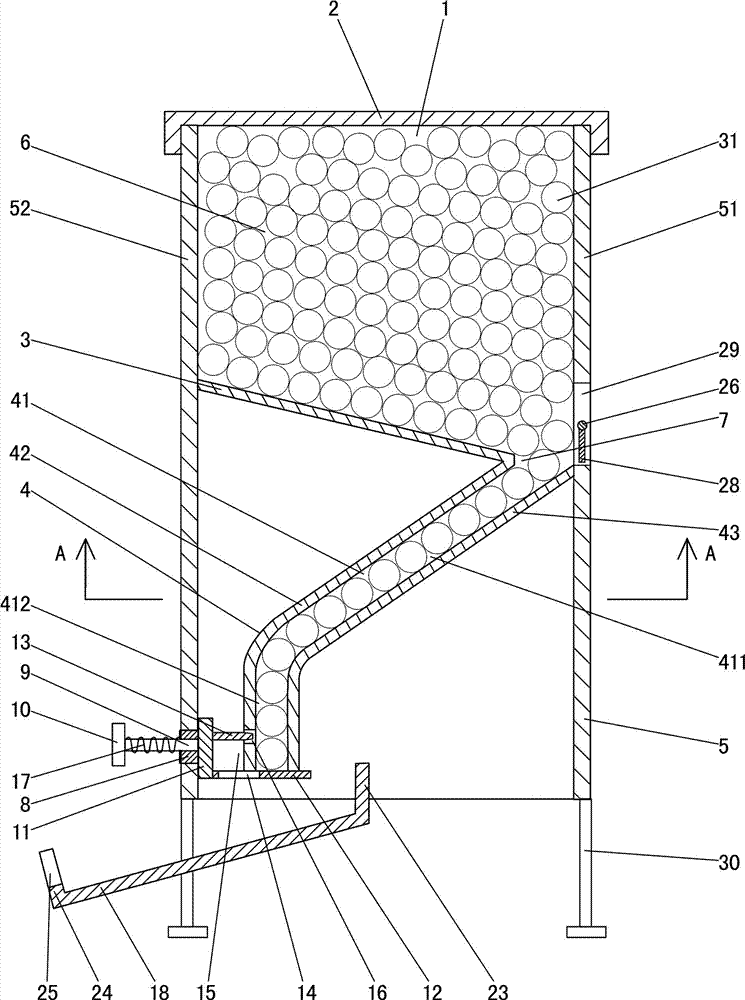
[0021] Such as figure 1As shown, this syringe storage device includes a box body 5, a box cover 2, a partition plate 3, a sliding guide part 4 and a separation and removal mechanism; the box cover 2 is covered on the opening 1 at the upper end of the box body 5; the partition plate 3 Set in the box body 5, the part of the box body 5 cavity located above the partition plate 3 constitutes the storage chamber 6, the upper surface of the partition plate 3 gradually slopes downward from front to back, and the rear edge of the partition plate 3 is in contact with the box body 5 The gap between the rear side walls 51 of the storage cavity constitutes the discharge port 7 of the storage chamber; the slide guide part 4 is arranged in the box body 5 and is below the partition plate 3, and the slide guide part 4 has a slide channel 41, and the slide channel 41 The inlet at the upper end communicates with the storage chamber 6 through the storage cavity discharge port 7; the upper part of...


PUM


Abstract

An injector storage device comprises a box body, a box cover, a partition plate, a slipping guide component and a separating and taking-out mechanism. A storage cavity is formed in the portion, located above the partition plate, in a cavity of the box body, and a discharge port of the storage cavity is formed by the gap between the rear edge of the partition plate and the rear side wall of the box body; a slipping channel is formed in the slipping guide component, and the upper end of the slipping channel is communicated with the storage cavity; the separating and taking-out mechanism comprises a guide sleeve, a guide rod, a pressing plate, a limiting wallboard, a layer board and an inserting plate, the guide sleeve is arranged on the front side wall of the box body, the guide rod is located in the guide sleeve, the limiting wallboard is connected with the rear end of the guide rod, the layer board and the inserting plate are connected with the limiting wallboard, the rear of the layer board is located below the slipping guide component, a material falling opening is formed in the front of the layer board, the inserting plate is located over the material falling opening, a gap is formed between the inserting plate and the layer board, and an inserting opening is formed in the front side of a vertical slipping section of the slipping channel. The injector storage device can store injectors, the injectors can be taken out one by one conveniently when needed, and it can be avoided that the injectors are expired.

Description

technical field [0001] The invention relates to medical auxiliary equipment, in particular to a syringe storage device. Background technique [0002] At present, in hospitals, syringes are usually stored in the original packaging boxes from the factory, and most of them are placed in corners such as walls and tables in medical workstations; when necessary, medical staff take them out of the packaging box one by one, or take them out of the packaging box at one time Multiple syringes are placed on the table or tray, and then taken one by one from the table or tray. In addition, when there are only a few syringes left in the packing box, some medical staff are used to adding new syringes to it, and syringes with different production dates are often mixed together. [0003] The above method of storing and taking the syringes has the following disadvantages: (1) The storage and taking are relatively random, and the syringes cannot be taken sequentially according to the producti...

Claims


Application Information

Patent Timeline
Patent Type & Authority Applications(China)
IPC IPC(8): A61B19/02A61G12/00B65D83/00
Inventor 汤秀云汤银惠许志军
Owner THE FIRST AFFILIATED HOSPITAL OF SHANTOU UNIV MEDICAL COLLEGE
Why Eureka
Try Eureka