Drying and temperature-controlling device for ballast and operating method thereof

A ballast and drying technology, applied in the direction of ballast layer, road, track, etc., can solve the problems of ballast track bed drying, and achieve the effect of improving drying and temperature control efficiency and small thermal inertia.

Inactive Publication Date: 2014-10-29
COVESTRO DEUTSCHLAND AG
View PDF8 Cites 11 Cited by
  • Summary
  • Abstract
  • Description
  • Claims
  • Application Information

AI Technical Summary

Problems solved by technology

However, the method disclosed in WO2006031841A2 cannot be used to dry the ballasted track bed due to the

Method used


Image

  • Drying and temperature-controlling device for ballast and operating method thereof
  • Drying and temperature-controlling device for ballast and operating method thereof
  • Drying and temperature-controlling device for ballast and operating method thereof

Examples


Embodiment 1

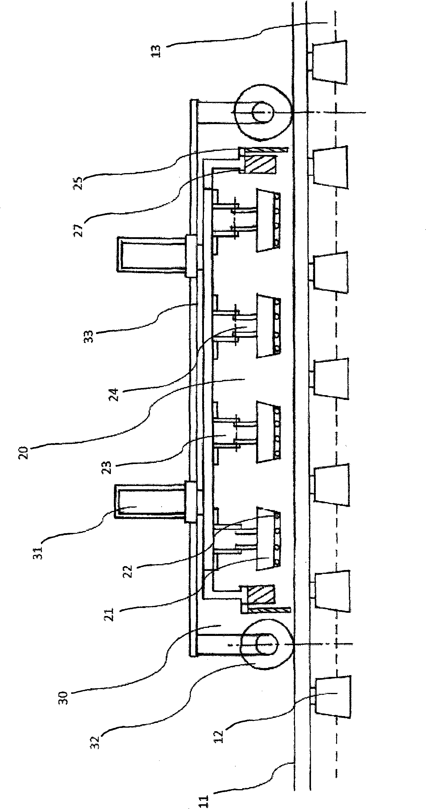
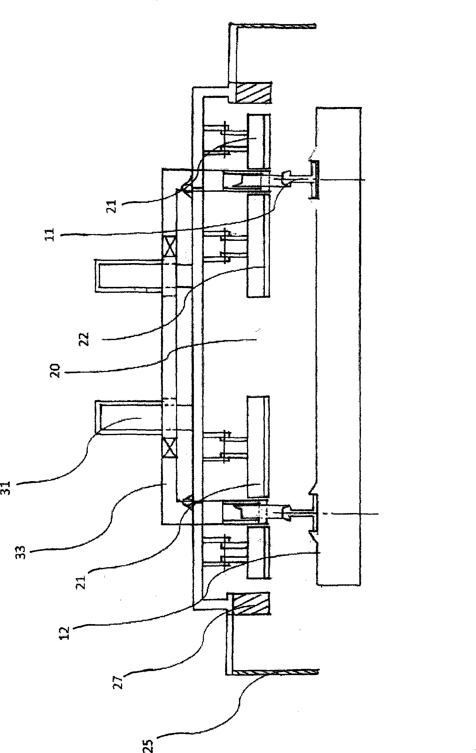
[0047] See Figure 4 , The microwave heating part 20 of the device of the present invention can be selected as a household small magnetron 23 of 2540MHz, and the power of the magnetron is 2KW to 5KW. This kind of magnetron is small in size, and can form a small microwave generator together with the waveguide 24 , the radiating resonant cavity 21 and the homogenizer 22 , and output microwaves from the homogenizer 22 . In this embodiment, the microwave heating component 20 is composed of a series of small microwave generators connected in series and parallel. Such as Figure 4 As shown, the microwave heating unit 20 includes four rows of microwave heating generators equally spaced, and the space is approximately equal to the space between sleepers. Each row of microwave generators consists of four microwave generators, which are symmetrically distributed along the centerline of the rail. For example, in Figure 4 Among them, the larger microwave generators are symmetrically ...

Embodiment 2

[0049] See Figure 5 , The microwave heating part 20 of the device of the present invention can be selected the industrial large-scale magnetron 29 of 915MHz, and the power of this magnetron is 75KW to 100KW. Due to the huge volume of the 915MHz magnetron, this magnetron can be arranged at the rear end of the microwave heating component 20 . Generally speaking, in order to avoid waste of microwaves, 2 to 4 magnetrons 29 can be connected in series and parallel according to the construction speed requirements, and the microwaves can be introduced into the radiation type resonant cavity 21 and homogenizer 22 through the bifurcated waveguide combination 281 .

[0050] Such as Figure 5 As shown, one end of the bifurcated waveguide assembly 281 is connected to the resonant cavity 21, and the other end is connected to the magnetron 29 through the circulator 282. In this technical field, a circulator is a non-reciprocal transmission element, usually used to connect a microwave sour...


PUM


Abstract

The invention relates to a drying and temperature-controlling device for ballast. The device comprises a microwave heating component (20) and a temperature-controlling component (40). The microwave heating component (20) supplies microwaves to the ballast so as to remove moisture in the ballast. The temperature-controlling component (40) supplies hot air or cold air so as to adjust the ballast to the preset temperature. The invention further relates to an operating method of the drying and temperature-controlling device. The method comprises the steps that a lifting mechanism (30) is used for enabling the microwave heating component (20) to descend to the descending position, the microwave heating component (20) is driven to supply microwaves to the ballast so as to remove moisture in the ballast, the temperature-controlling component (40) is utilized for supplying hot air and/or cold air so as to adjust the ballast to the preset temperature, and the lifting mechanism (30) is used for enabling the microwave heating component (20) to ascend to the ascending position. Due to the fact that the microwave heating technology and the convective heating technology are combined to be used, the drying and temperature-controlling efficiency of a ballast bed and the ballast is greatly improved.

Description

technical field [0001] The invention relates to a device for drying and controlling the temperature of ballast in a ballasted track bed, and an operation method of the device. Specifically, the present invention relates to a device and an operation method for drying and controlling the temperature of ballast in a ballasted track bed by combining microwaves and conventional heating methods. Background technique [0002] The ballasted track bed usually refers to the ballast layer laid between the sleepers and the subgrade. It is the foundation of the rail frame, and its main function is to support the sleepers, and evenly distribute the huge railway vehicle loads from the rails and sleepers to the subgrade surface, so as to reduce the deformation of the subgrade and ensure driving safety. In addition, the ballast layer also has the function of cushioning and shock absorption. The ballasted track bed has good versatility, a long history of use, and low construction costs. Th...

Claims


Application Information

Patent Timeline
IPC IPC(8): E01B27/00
Inventor 张晨曦
Owner COVESTRO DEUTSCHLAND AG
Why Eureka
Try Eureka