
Automatic control energy-saving system and control method

An energy-saving system and control method technology, applied in pipeline systems, mechanical equipment, gas/liquid distribution and storage, etc., can solve the problems of increasing energy consumption of running air compressors, increasing false demand, frequent loading and unloading of air compressors, etc. , to achieve the effect of reducing energy consumption and stabilizing pressure

Inactive Publication Date: 2014-10-29
NINGBO MOMI INNOVATION WORKS ELECTRONICS TECH
View PDF6 Cites 3 Cited by
  • Summary
  • Abstract
  • Description
  • Claims
  • Application Information

AI Technical Summary

Problems solved by technology

[0003] Compressed gas is supplied to various workshops through high-pressure pipelines and low-pressure pipelines. Generally speaking, the amount of high-pressure compressed air and low-pressure compressed air used in the factory area fluctuates, but for normal production, there is often a certain margin, and the unloading capacity of the air compressor The consumption is 30-60% of the loaded energy consumption, and the air compressor does not produce gas, which will increase a certain amount of energy waste; since the entire compressed air delivery and distribution system is divided into two systems, high-pressure delivery and low-pressure delivery, each system Increased false demand, resulting in frequent loading and unloading of the air compressor, increasing the energy consumption of the operating air compressor, and affecting the pressure stability of the compressed air system

Method used


Image

  • Automatic control energy-saving system and control method

Examples


Embodiment Construction

[0026] In order to make the purpose, technical solution and advantages of the present invention clearer, the technical solution of the present invention will be clearly and completely described below in conjunction with specific embodiments of the present invention and corresponding drawings.

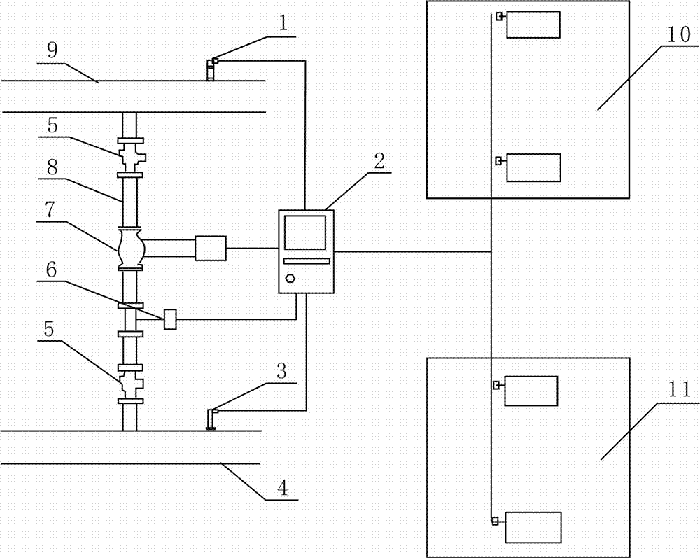
[0027] refer to figure 1 , figure 1 Shown is the connection diagram of the automatic control energy-saving system of this embodiment; the system includes a low-pressure pipeline 4, a high-pressure pipeline 9, a high-pressure air compressor unit 10, a low-pressure air compressor unit 11, a connecting pipeline 8, a first pressure transmission Device 1, second pressure transmitter 3, optimization control module 2, regulating valve 7, flow meter 6 and ball valve 5.

[0028] The high-pressure pipeline 9 is connected to the high-pressure air compressor unit 10, the low-pressure pipeline 4 is connected to the low-pressure air compressor unit 11, and the first pressure transmitter 1 is install...


PUM


Abstract

The invention discloses an automatic control energy-saving system. The automatic control energy-saving system comprises a high-pressure pipeline, a low-pressure pipeline, a connecting pipeline, an adjusting valve installed on the connecting pipeline, a flowmeter communicated with the connecting pipeline, a first pressure transmitter arranged on the high-pressure pipeline, a second pressure transmitter arranged on the low-pressure pipeline, and an optimal control module. A high-pressure air compressor unit, a low-pressure air compressor unit, the first pressure transmitter, the second pressure transmitter, the adjusting valve and the flowmeter are connected with the optimal control module. By means of the automatic control energy-saving system, the running state of air compressors can be grasped in time, the optimal pressure states of pressure of compressed air in the high-pressure pipeline and the pressure of the compressed air in the low-pressure pipeline can be guaranteed, the pressure of the compressed air can be stabilized, the demands of the compressed air can be accurately detected, the running of the air compressors can be reasonably arranged, and the energy consumption can be reduced by about 10 percent.

Description

technical field [0001] The invention relates to an automatic control energy-saving system and a control method. Background technique [0002] Considering the actual situation, the factory areas that currently use more compressed air generally use high-pressure pipelines that deliver compressed gas with higher pressure and low-pressure pipelines that deliver compressed gas with lower pressure. [0003] Compressed gas is supplied to various workshops through high-pressure pipelines and low-pressure pipelines. Generally speaking, the amount of high-pressure compressed air and low-pressure compressed air used in the factory area fluctuates, but for normal production, there is often a certain margin, and the unloading capacity of the air compressor The consumption is 30-60% of the loaded energy consumption, and the air compressor does not produce gas, which will increase a certain amount of energy waste; since the entire compressed air delivery and distribution system is divided ...

Claims


Application Information

Patent Timeline
IPC IPC(8): F17D1/04F17D3/01
Inventor 刘霖张杨鹏古家顺
Owner NINGBO MOMI INNOVATION WORKS ELECTRONICS TECH
Learn More