A target track space reference device and its adjustment method

A reference device and target track technology, applied in the direction of offensive equipment, weapon accessories, weapon testing, etc., can solve problems such as difficult to guarantee, high precision, etc., and achieve the effect of difficult to solve, convenient and precise adjustment, and strong stability

Inactive Publication Date: 2015-09-23
NANJING UNIV OF SCI & TECH
View PDF5 Cites 0 Cited by
  • Summary
  • Abstract
  • Description
  • Claims
  • Application Information

AI Technical Summary

Problems solved by technology

In this method, it is difficult to collimate the light spot emitted by the laser device to be relatively small and relatively round, and it is also difficult to ensure high accuracy through visual inspection.

Method used


Image

  • A target track space reference device and its adjustment method
  • A target track space reference device and its adjustment method
  • A target track space reference device and its adjustment method

Examples


Embodiment 1

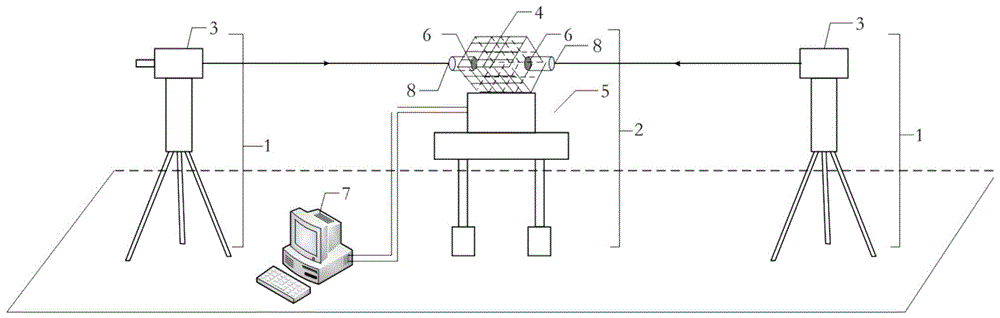
[0027] Taking the 200m target lane as an example, two sets of identical laser emission stations 1, one set of laser emission stations 1 are placed in the target path shooting room, and the other group of laser emission stations 1 are placed at the end of the target path, and will be located at the end of the target path shooting room. The laser emitting end of the collimator 3 of the laser emitting station 1 is kept at the same height as the line of fire of the gun barrel, and the precision displacement stage is adjusted so that the laser beam generated by the collimator 3 is in the direction of the line of fire of the gun barrel.

[0028]Based on the laser beams generated by the laser emitting station 1 in the shooting room of the target path, a spot coincidence detection device is installed in the middle of the two groups of laser emitting stations 1, and the precision displacement platform of the laser emitting station 1 at the end of the target path is adjusted so that the ...

Embodiment 2

[0031] Taking the 100m target lane as an example, two sets of identical laser emission stations 1, one group of laser emission stations 1 are placed in the target path shooting room, and the other group of laser emission stations 1 are placed at the end of the target path, and will be located at the end of the target path shooting room. The laser emitting end of the collimated light source 3 based on the laser of the laser transmitting station 1 is kept at the same height as the line of fire of the gun barrel, and the precision displacement stage is adjusted so that the laser beam based on the collimated light source 3 of the laser is on the line of fire of the barrel.

[0032] Based on the laser beams generated by the laser emitting station 1 in the shooting room of the target path, a spot coincidence detection device is installed in the middle of the two groups of laser emitting stations 1, and the precision displacement platform of the laser emitting station 1 at the end of t...


PUM


Abstract

The invention discloses a target lane space benchmark device and an adjusting method of the target lane space benchmark device. According to the target lane space benchmark device and the adjusting method of the target lane space benchmark device, based on a laser, a PSD, a precise multi-dimensional stepping motor console and the like, the position of a laser beam is sensed through the PSD, a light spot position signal is converted into an electric signal, according to the generated electric signal, the operation direction and stepping of a stepping motor are controlled, the multi-dimensional stepping motor console is driven to operate, the central position of the PSB is accurately irradiated with a front laser spot and a rear laser spot, and therefore a trajectory target lane space benchmark system is established. By the adoption of the target lane space benchmark device and the adjusting method of the target lane space benchmark device, the laser beams are located in the direction of a firing line of a gun muzzle or a muzzle and are horizontal, and the standard reference point of a mesh shaped like the Chinese character 'tian' is accurately irradiated with the laser beams; in addition, it is avoided that an experimenter conducts visual inspection of the positions of the light spots, the energy density center of each light spot can be accurately measured through the PSD installed on the mesh shaped like the Chinese character 'tian', and the requirements for the diameter of each light spot and the quality are lowered.

Description

technical field [0001] The invention belongs to the technical field of test and measurement, and in particular relates to a target track space reference device and an adjustment method thereof. Background technique [0002] The ballistic target plays a very important role in the design and research of various conventional projectiles, and has become an indispensable test method. The high-precision time and space reference is the main feature of the ballistic target. The level of the space reference device of the traditional ballistic target trajectory is generally realized through the water tank of the connector, and the shooting direction is provided through the catenary line. During calibration, the level and shooting direction are adjusted by observing the telescopic device with human eyes, so that The grid is at the standard position of the camera station. Due to the large randomness of this method, especially long-distance catenary lines are difficult to erect. Theref...

Claims


Application Information

Patent Timeline
Patent Type & Authority Patents(China)
IPC IPC(8): F41A31/00
Inventor 顾金良徐伟龙罗红娥夏言陈平王维沈华
Owner NANJING UNIV OF SCI & TECH
Why Eureka
Try Eureka