Control device for internal combustion engine

A technology of a control device and an internal combustion engine, which is used in engine control, internal combustion engine testing, internal combustion piston engines, etc., can solve problems such as difficult internal combustion engines and high compression ratios, and achieve the effect of reducing computational load and achieving high precision.

Inactive Publication Date: 2014-10-29
HITACHI AUTOMOTIVE SYST LTD
View PDF7 Cites 5 Cited by
  • Summary
  • Abstract
  • Description
  • Claims
  • Application Information

AI Technical Summary

Problems solved by technology

It is difficult to increase the compression ratio of an internal combustion engine without avoiding at least these knocks and misfires

Method used


Image

  • Control device for internal combustion engine
  • Control device for internal combustion engine
  • Control device for internal combustion engine

Examples


Embodiment 1

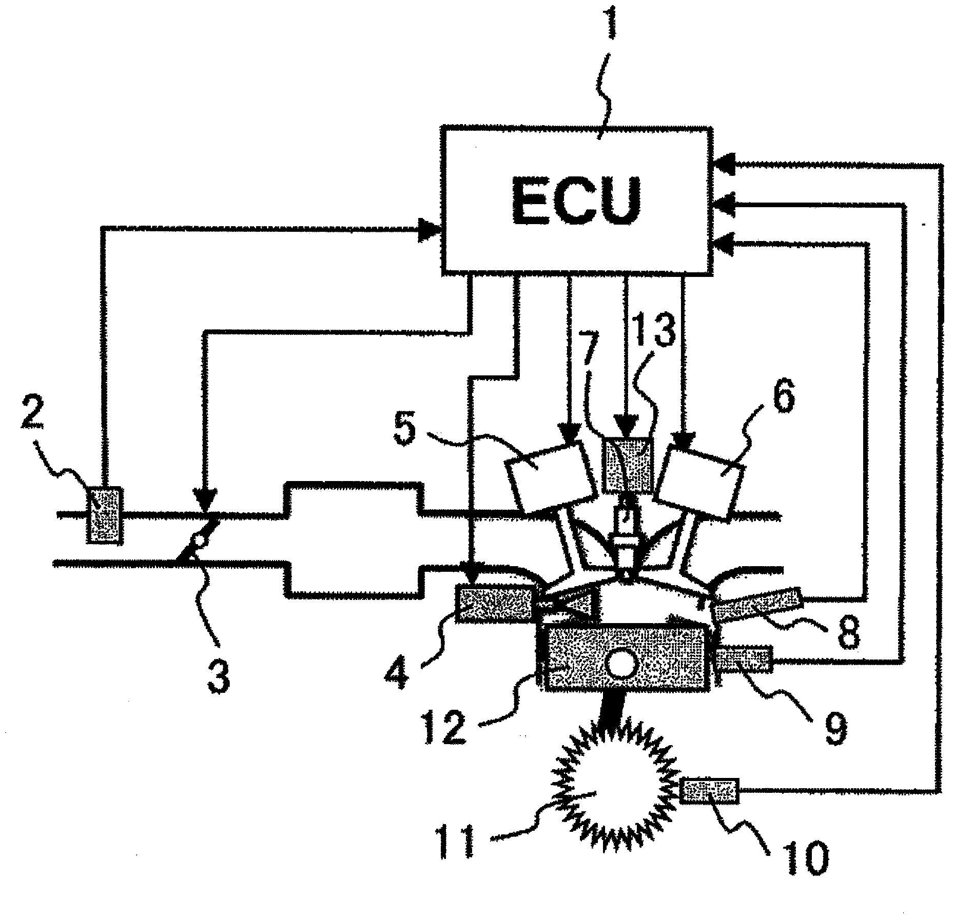
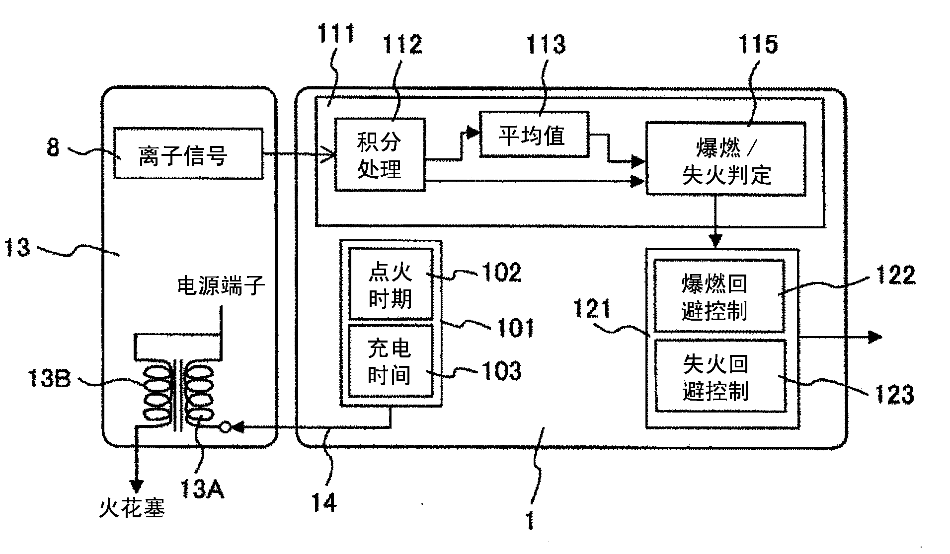
[0050] figure 2 It is a diagram showing processing blocks of input and output signals of a control device for an internal combustion engine (hereinafter, simply referred to as a control device) according to an embodiment of the present invention. In the control device 1, based on input signals from various sensors, the ignition timing calculation module 102 calculates the ignition timing, and the charging time calculation module 103 calculates the energy required for the ignition, that is, the charging time of the primary current. An ignition signal 14 in which the ignition timing and charging time are paired is output to the ignition coil 13 .

[0051] The ignition coil 13 is composed of a primary coil 13A and a secondary coil 13B. The upper end of the primary coil 13A is connected to a power source, and the lower end of the primary coil 13A is configured to receive an ignition signal 14 . Detailed descriptions of generally used transistors and other drive circuits are omit...

Embodiment 2

[0098] Next, other embodiments of the present invention will be described in detail using the drawings. Figure 9 It is a configuration in which the ion signal integration processing module 112 of the ion signal processing unit 111 shown in the first embodiment is changed to the ion signal peak detection module 116 .

[0099] The operation of this second embodiment is basically the same as that of the first embodiment, but differs in that the ion signal peak detection module 116 is used as described above.

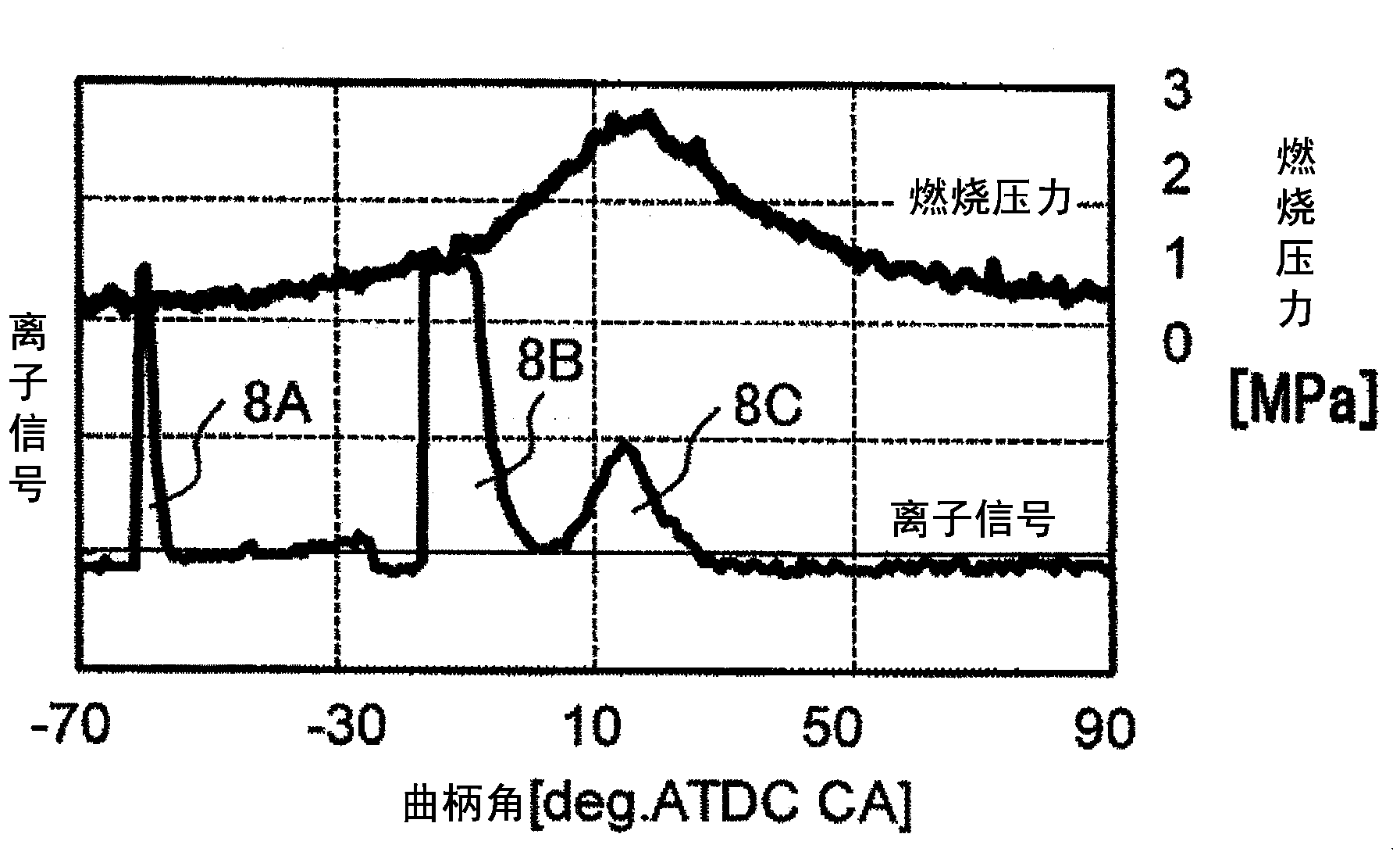
[0100] Next, if the action is simply explained, then Figure 10 for with Figure 4 The waveform of the same ion signal shows the relationship between the ignition signal 14 and the ion signal 8 . Ignition signal 14 is input at time T1 to start charging for accumulating ignition energy in primary coil 13A. image 3 The noise waveform described in is the first peak 8A. This peak 8A is not used for detection of knocking or misfire because it is noise caused by the ignitio...


PUM


Abstract

Conventional control devices for internal combustion engines had the issue of high arithmetic loads in the control device (1), as a result of using different sensors and different detection mechanisms to detect knocking and misfiring. Also, reducing the gaps of delay in ignition timing was effective from the perspective of improving internal combustion engine efficiency, however trace knock detection was required for this. The present invention is configured so as to: detect combustion ions generated inside the combustion chamber, using an ion sensor; integrate this ion signal and find an integrated signal; compare this integrated signal to a misfire determination value and a knock determination value that is based on a signal averaging the integrated signals for a prescribed number of past cycles; and determine knocking and misfiring. Ignition timing control can be more precise, as a result of: a reduced arithmetic load because misfiring and knocking are detected by the same ion sensor and determination processing is performed using the same determination function logic; and the setting of a knock determination threshold which facilitates trace knock detection.

Description

technical field [0001] The present invention relates to a control device for an internal combustion engine, and more particularly to a control device for an internal combustion engine capable of accurately estimating the knock state and misfire state of the internal combustion engine by detecting the combustion state in a cylinder as an ion signal. Background technique [0002] In recent years, due to the increase in fuel consumption of motor vehicles, attempts to improve the combustion efficiency of internal combustion engines have been required. One of such improvement technologies is increasing the compression ratio, and it has been theoretically proven that the thermal efficiency of the internal combustion engine can be improved by increasing the compression ratio of the internal combustion engine. [0003] A spark ignition type internal combustion engine using gasoline has a compression ratio of about 10, and a diesel type internal combustion engine has a compression ra...

Claims


Application Information

Patent Timeline
Patent Type & Authority Applications(China)
IPC IPC(8): F02D45/00F02P17/12
CPCF02P17/12F02D2200/1015F02D35/027F02D35/021F02P3/02F02P5/152F02P2017/128F02P3/045G01M15/11Y02T10/40F02P5/04
Inventor 白石拓也熊野贤吾绪方健一郎赤城好彦真户原伸也
Owner HITACHI AUTOMOTIVE SYST LTD
Why Eureka
Try Eureka