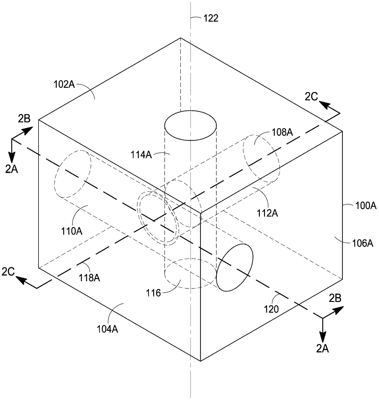
Additive injection zone valve
A technology of additives and input ports, which is applied in the direction of valve devices, sliding valves, mechanical equipment, etc., can solve the problem of reducing product quality, such as undesired gel formation, etc.
- Summary
- Abstract
- Description
- Claims
- Application Information
AI Technical Summary
Problems solved by technology
Method used
Image
Examples
Embodiment 1
[0062] Example 1. Comparative example. No gradual transition.
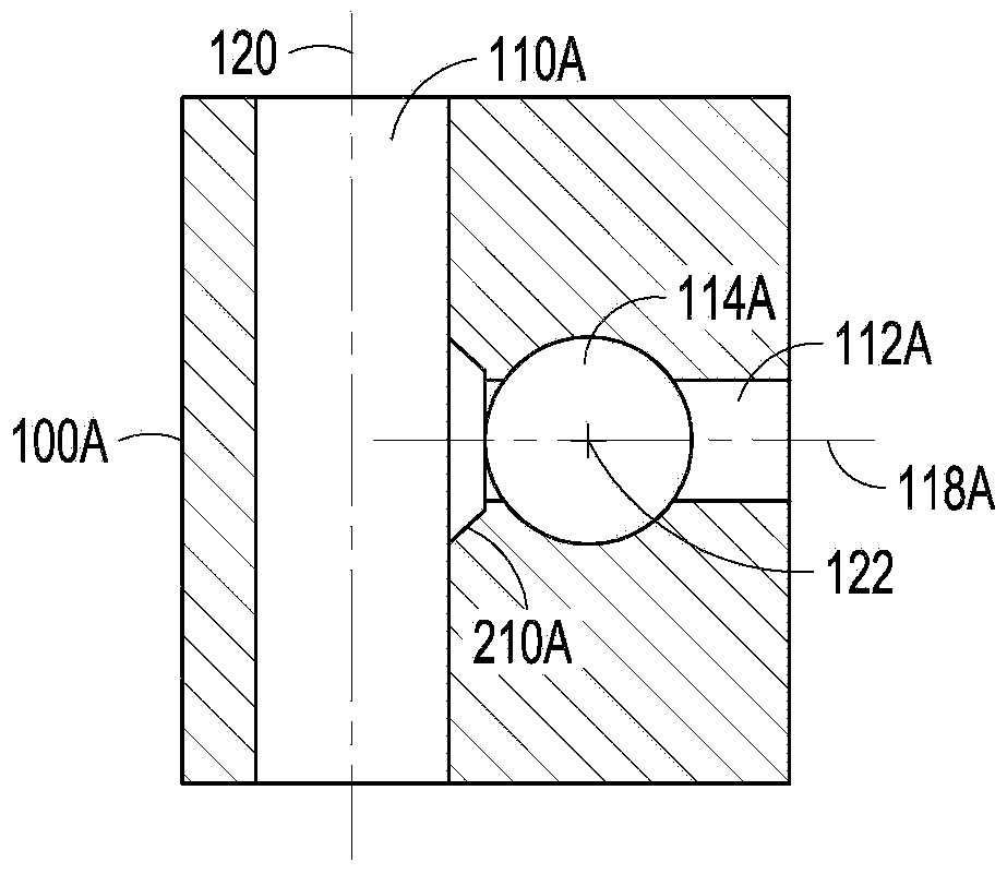
[0063] A continuous polymerization process is carried out. The main channel of the valve body meets the output channel at a flat angle. In this embodiment, no bevels, bends or tapers are provided at the points of intersection; rather, the walls of the main and output channels form with each other an angle determined by the angle formed between the transverse body axis and the transverse axis .
[0064] Eddy currents near the intersection of the main channel and the output channel cause gel formation. Gel formed at a rate of 0.1 g / day requiring the valve to be taken out of service for cleaning every 50 days to remove 10 g of gel from the output channel and from the main channel adjacent to the intersection of the output channel.
Embodiment 2
[0065] Example 2. Valve including gradual transition.
[0066] A continuous polymerization process is carried out. The main channel of the valve body intersects the output channel with rounded edges along the entire transition from the main channel to the output channel, where the curvature of the corners conforms to a 2 cm diameter circle. The transition from the main channel to the output channel occurs along a length of 1 cm of the main channel and along a length of 1 cm of the output channel extending from the main channel in each direction.
[0067] Eddy currents are reduced near the intersection of the main channel and the output channel. Gel formed at a rate of 0.03 g / day requiring the valve to be taken out of service for cleaning every 333 days to remove 10 g of gel from the output channel and from the main channel adjacent to the intersection of the output channel.
Embodiment 3
[0068] Example 3. Valve including gradual transition.
[0069] A continuous polymerization process is carried out. The main channel of the valve body intersects the output channel with two flat bevels extending along the entire radius of the transition from the main channel to the output channel, each bevel 0.7 wide and 158° from each of the two surfaces intersected by the bevel degree angle. The transition from the main channel to the output channel occurs along a length of 1 cm of the main channel and a length of 1 cm of the output channel in each direction extending along the main channel.
[0070] Eddy currents are reduced near the intersection of the main channel and the output channel. Gel formed at a rate of 0.04 g / day requiring the valve to be taken out of service for cleaning every 250 days to remove 10 g of gel from the output channel and from the main channel adjacent to the intersection of the output channel.
PUM
| Property | Measurement | Unit |
|---|---|---|
| length | aaaaa | aaaaa |
| diameter | aaaaa | aaaaa |
| density | aaaaa | aaaaa |
Abstract
Description
Claims
Application Information
 - R&D
- Intellectual Property
- Life Sciences
- Materials
- Tech Scout
- Unparalleled Data Quality
- Higher Quality Content
- 60% Fewer Hallucinations
Browse by: Latest US Patents, China's latest patents, Technical Efficacy Thesaurus, Application Domain, Technology Topic, Popular Technical Reports.
© 2025 PatSnap. All rights reserved.Legal|Privacy policy|Modern Slavery Act Transparency Statement|Sitemap|About US| Contact US: help@patsnap.com


