Supercharge Your Innovation With Domain-Expert AI Agents!

Valve cover injection mould

A technology for injection molds and valve covers, applied in the field of injection molds, can solve problems such as shortened service life of molds, easy collision, low precision of fixed and movable templates, etc., and achieve the effect of high speed and high efficiency

Inactive Publication Date: 2014-11-05
上海伟阳纸业有限公司
View PDF1 Cites 3 Cited by
  • Summary
  • Abstract
  • Description
  • Claims
  • Application Information

AI Technical Summary

Problems solved by technology

The injection mold is not equipped with a reset mechanism, so the accuracy of the cooperation between the fixed platen and the movable platen is not high. If the movable platen and the push plate are not careful during use, they are easy to collide, and the service life of the mold will be shortened.

Method used


Image

  • Valve cover injection mould

Examples


Embodiment Construction

[0016] In order to make the technical means, creative features, goals and effects achieved by the present invention easy to understand, the present invention will be further described below in conjunction with specific embodiments.

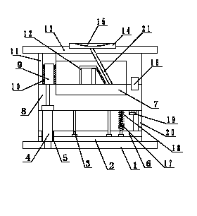
[0017] Such as figure 1 As shown, a valve cover injection mold includes a movable mold base plate 1, a movable mold plate 8, a fixed mold base plate 13 and a fixed mold plate 11. The movable mold base plate 1 is provided with a push plate 2, and the push plate 2 is provided with a through To the push rod 3 in the movable formwork 8, the push rod fixing plate 6 for fixing the push rod 3 is arranged on the push plate 2, the pad 20 is arranged between the push rod fixing plate 6 and the movable template 8, and the movable mold seat plate 1 The push plate guide column 4 passing through the push plate 2 is arranged on the top, the movable mold core 7 is arranged in the movable template 8; the fixed template 11 is arranged on the fixed mold seat plate 1...


PUM


Abstract

The invention discloses a valve cover injection mould which includes a movable mould seat plate, a movable mould plate, a fixed mould seat plate and a fixed mould plate. The movable mould seat plate is provided with a pushing plate. The pushing plate is provided with a pushing rod which penetrates into the movable mould plate. The pushing plate is provided with a pushing rod fixing plate which allows the pushing rod to be fixed. A cushion block is disposed between the pushing rod fixing plate and the movable mould plate. The movable mould seat plate is provided with a pushing plate guide column which penetrates through the pushing plate. A movable mould core is disposed in the movable mould plate. The fixed mould plate is arranged on the fixed mould seat plate and is provided with a fixed mould guide column. The fixed mould plate is matched with and connected to the movable mould plate through the fixed mould guide column. A fixed mould core is arranged in the fixed mould plate. The fixed mould seat plate is provided with a sprue sleeve. A positioning ring is disposed on the fixed mould seat plate. The sprue sleeve is disposed in the positioning ring. The pushing rod fixing plate is provided with a return rod. A flow pass is arranged in the fixed mould seat plate and the fixed mould plate and is communicated with the sprue sleeve and the fixed mould core. The valve cover injection mould is simple in structure and is convenient to use. Through arrangement of a return mechanism, the injection mould is high in precision and efficiency.

Description

technical field [0001] The invention relates to an injection mold, in particular to a valve cover injection mold. Background technique [0002] In the prior art, such as patent ZL201110412074.2 discloses an injection mold, the injection mold includes a fixed template and a movable template, a core-pulling mechanism is provided on the movable template, and a locking member is provided on the outside of the fixed template. The moving template is connected with the core-pulling mechanism and is provided with a locking member fixing seat. One end of the locking member is connected with the fixed template, and the other end is movably connected with the locking member fixing seat. Moreover, when the injection mold is in the mold clamping state , the locking member and the fixing seat of the locking member are in a connected state, which can prevent the core pulling mechanism from being knocked back due to excessive injection force during the injection molding process. The inject...

Claims


Application Information

Patent Timeline
Patent Type & Authority Applications(China)
IPC IPC(8): B29C45/26B29C45/36
CPCB29C45/2602B29C45/2606
Inventor 程齐
Owner 上海伟阳纸业有限公司
Features
  • R&D
  • Intellectual Property
  • Life Sciences
  • Materials
  • Tech Scout
  • Unparalleled Data Quality
  • Higher Quality Content
  • 60% Fewer Hallucinations
Learn More