
Composite pipe joint and manufacturing method thereof

A composite pipe and intubation technology, which is applied in the direction of pipes/pipe joints/fittings, hose connection devices, mechanical equipment, etc. The problems of pressing the skeleton layer and the damage of the intubation structure can achieve the effect of simple process and high connection strength.

Inactive Publication Date: 2014-11-05
河北宏广橡塑金属制品有限公司
View PDF4 Cites 4 Cited by
  • Summary
  • Abstract
  • Description
  • Claims
  • Application Information

AI Technical Summary

Problems solved by technology

The composite pipe joint of this structure has the following defects: first, the inner diameter of the intubation tube that constitutes the joint is smaller than the inner diameter of the composite pipe, causing the problem that the pipe diameters of the composite pipe joint and the composite pipe are inconsistent; For pipe joints, the external pressure ferrule is directly placed on the outside of the intubation tube inserted with the composite tube - when the diameter of the external pressure ferrule is small, it can meet the connection strength of the connection part, but due to the extremely high pressure during insertion, it will The inner tube layer, the middle pressure-bearing skeleton layer and the intubation structure of the composite pipe are damaged; when the diameter of the external pressure ferrule is large, although it is beneficial to the inner tube layer, the middle pressure-bearing skeleton layer and the intubation structure of the composite pipe protection, but its connection strength is difficult to guarantee

Method used


Image

  • Composite pipe joint and manufacturing method thereof
  • Composite pipe joint and manufacturing method thereof

Examples


Embodiment Construction

[0025] The structure of the composite pipe special joint provided by the present invention will be further described in detail below in conjunction with the accompanying drawings.

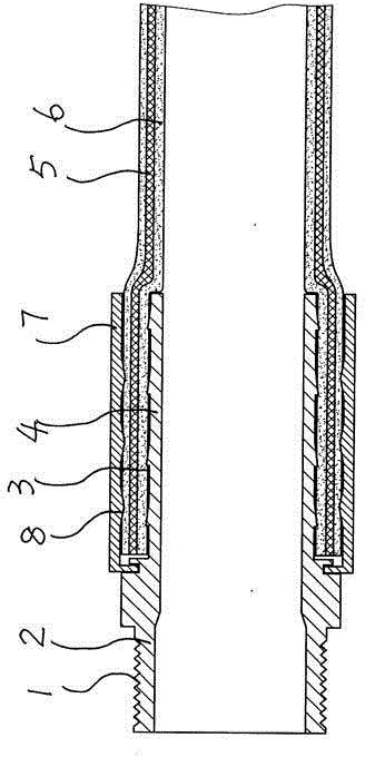
[0026] Such as figure 1 Shown is the structural schematic diagram of the special joint for composite pipe provided by the present invention. The structure constituting the special joint for the composite pipe includes a connecting section 2 provided with a connecting mechanism 1 and a plug composed of an inverted toothed ring 3 and an intubation tube 4 integrated therewith. The insertion tube is inserted into the inner tube 6 that constitutes the composite tube 5. The external pressure pipe clamp 7 is arranged on the outside of the cannula inserted into the inner tube; and the inner pipe diameter of the cannula is the same as the inner pipe diameter of the composite pipe.

[0027] In the structure constituting the above-mentioned special joint for composite pipe:

[0028] ——The connecting mechanism 1 con...


PUM


Abstract

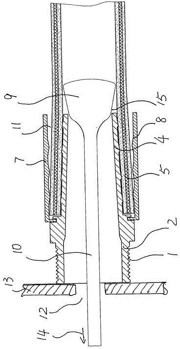
The invention belongs to the technical field of high-pressure rubber pipe joints and discloses a composite pipe joint used for high-pressure petroleum conveying and a manufacturing method of the composite pipe joint. According to the main technical scheme, the composite pipe joint comprises a connecting section provided with a connecting mechanism, and a plug formed by a plug pipe with an inverted-tooth ring, the connection section and the plug are of an integrated structure, the plug pipe is plugged into an inner pipe forming the composite pipe, and an outer pressing pipe hoop is arranged on the outer side of the plug pipe plugged into the inner pipe. The inner pipe diameter of the plug pipe is identical with the inner pipe diameter of the composite pipe. According to the composite pipe joint, a pull rod with an expansion head arranged at the end is plugged into the plug pipe, the outer press pipe hoop is arranged on the section of the plug pipe in a sleeved mode, the composite pipe is plugged into a formed cylinder ring, and the pull rod is pulled to expand the inner diameter of the plug pipe through the expansion head at the end of the pull rod, and thus the composite pipe joint is formed. The special composite pipe joint is manufactured with the method, the advantages that the structure is simple, the requirement for high pressure and connecting strength can be met, and the method is simple are achieved.

Description

Technical field [0001] The invention belongs to the technical field of high-pressure hose joints, and specifically relates to an oil-conveying composite pipe joint used for high-pressure petroleum transportation and a preparation method thereof. Background technique [0002] At present, the composite pipe is widely used to transport petroleum. Its structure includes an inner pipe layer for conveying high-pressure medium, an intermediate pressure-bearing skeleton layer composed of a steel wire winding braid layer and a middle rubber adhesive layer wrapped around it, and an outer rubber layer. The structure of the composite pipe connection joint includes a connecting section provided with an internal thread or an external thread to form a connecting mechanism and a plug composed of an inverted ring cannula integrated with it. The end of the composite pipe is inserted into the plug The intubation tube is formed with an external pressure pipe clamp on the outside. The composite pipe...

Claims


Application Information

Patent Timeline
Patent Type & Authority Applications(China)
IPC IPC(8): F16L33/035
CPCF16L33/20
Inventor 张春建
Owner 河北宏广橡塑金属制品有限公司
Learn More