IC card swiping machine

A technology of a card swiping machine and a support rod, applied in the field of card swiping machines, can solve the problems of loose fixing of the card swiping machine, damage and failure of the card swiping machine, etc., and achieve the effect of convenient card swiping operation, convenient fixed installation, maintenance and replacement, and reminding recharge and payment.

Inactive Publication Date: 2014-11-05
MIANYANG MIANZHOUTONG
View PDF6 Cites 0 Cited by
  • Summary
  • Abstract
  • Description
  • Claims
  • Application Information

AI Technical Summary

Problems solved by technology

During driving, especially on bumpy roads, the body shakes violently, which makes the fixing of the card reader easy to loosen, which in turn leads to damage or direct failure of the card reader; and the existing card reader is fixed by welding or clamps. , when replacing or repairing the credit card machine, it can only be dismantled by cutting or violent destruction, resulting in a large waste of materials

Method used


Image

  • IC card swiping machine

Examples


Embodiment 1

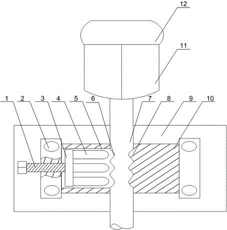
[0021] like figure 1 As shown, this embodiment includes threaded support rods 7 and mounting bases 10 on the outer walls of the upper and lower ends. The middle part of the mounting base 10 has a threaded through hole, and the support rod 7 passes through the threaded through hole, and the top of the support rod 7 is installed There is a credit card machine, and the middle part of the support rod 7 is provided with a plurality of spiral grooves 6, and the inner wall of one side of the threaded through hole is provided with a protrusion 8 matching the spiral groove 6, and the other side of the threaded through hole is provided with a protrusion 8. There is a movable cavity 5, and a base plate 3 is installed in the movable cavity 5, and a plurality of clamping rods 4 whose ends cooperate with the spiral groove 6 are arranged at intervals on the base plate 3, and there are movable rods 4 at the ends of the mounting base 10. The cavity 5 communicates with the threaded hole, and th...

Embodiment 2

[0024] like figure 1 As shown, on the basis of Embodiment 1, this embodiment also includes a mounting plate 9, a plurality of mounting holes 2 are opened at both ends of the mounting base 10, and the mounting plate 9 is arranged on the upper plate of the mounting base 10 through the mounting holes 2. Set on the mounting base 10 through the threaded hole. The traditional card reader is fixed on the support frame by welding, so that the support frame will be directly damaged when the card reader is damaged or maintained, resulting in a waste of resources and an increase in cost. On the seat 10, the card reader is installed on the fixed plate, and the fixing method can also be fixed by bolts and other movable connection methods, so that in each maintenance and replacement process, the mounting seat 10 can also be used for fixed connection and recycled to reduce The cost of using the credit card machine.

[0025] The end of the clamping rod 4 is U-shaped, conical or tooth-shaped...


PUM


Abstract

The invention discloses an IC card swiping machine which comprises a supporting rod and an installation base. A threaded through hole is formed in the middle of the installation base. The supporting rod penetrates through the threaded through hole. A plurality of spiral grooves are formed in the middle of the supporting rod. An activity cavity is formed in the other side of the threaded through hole. A bottom plate is installed in the activity cavity. A plurality of clamping and holding rods with the ends matched with the spiral grooves are arranged on the bottom plate at intervals. One end of the installation base is provided with a threaded hole communicated with the activity cavity. A screw is connected with the bottom plate through the threaded hole. The card swiping machine comprises a plurality of reader-writers and a display screen connected with the reader-writers, wherein the reader-writers are fixed to the top end of the supporting rod in an annular array mode. The portion, located at the top end of the supporting rod, of the card swiping machine is of an annular structure composed of the multiple reader-writers, and therefore cards can be swiped within the range of 360 degrees, and the card swiping operation of passengers is facilitated; the display screen electrically connected with the reader-writers can display information in the bus cards of the passengers and remind the passengers to recharge the cards to pay the fees.

Description

technical field [0001] The invention relates to a card swiping machine, in particular to an IC card swiping machine. Background technique [0002] The non-contact IC card bus toll system is the most advanced bus toll management system at present. It adopts the cutting-edge technology of radio frequency identification and is designed in combination with modern management methods. It has contact-free, loss-free, advanced technology, and system scalability. It is the best choice for public transport units to improve their management level and realize electronic control. It is widely used in urban public transport, vehicle charges for enterprises and institutions, school special vehicle charges, community special vehicle charges, etc. [0003] The bus card reader is the core construction part of the urban bus card and a part of the intelligent bus I system. It is composed of a vehicle toll terminal and a background management system, which greatly improves the service level of t...

Claims


Application Information

Patent Timeline
Patent Type & Authority Applications(China)
IPC IPC(8): G07F7/08
Inventor 李强李宝家
Owner MIANYANG MIANZHOUTONG
Why Eureka
Try Eureka