Camera displacement compensation method and device

A camera and current position technology, applied in the field of cameras, can solve the problem of high cost and achieve the effect of simple algorithm and easy implementation

Active Publication Date: 2014-11-05
ZHEJIANG UNIVIEW TECH CO LTD
View PDF4 Cites 19 Cited by
  • Summary
  • Abstract
  • Description
  • Claims
  • Application Information

AI Technical Summary

Problems solved by technology

However, optical anti-shake technology needs to be equipped with a special anti-shake lens or anti

Method used


Image

  • Camera displacement compensation method and device
  • Camera displacement compensation method and device
  • Camera displacement compensation method and device

Examples


Embodiment Construction

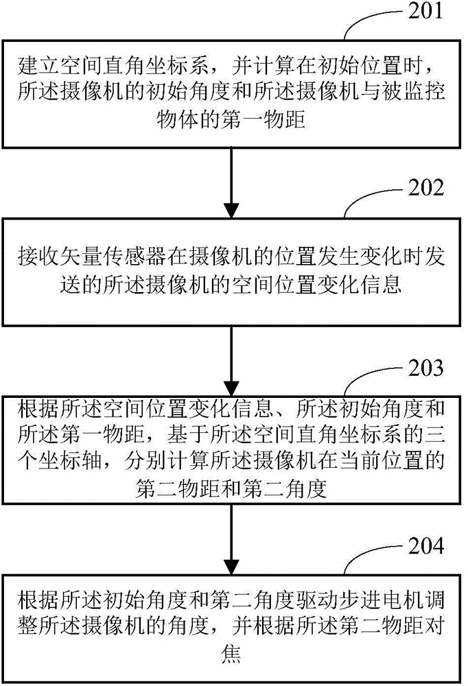
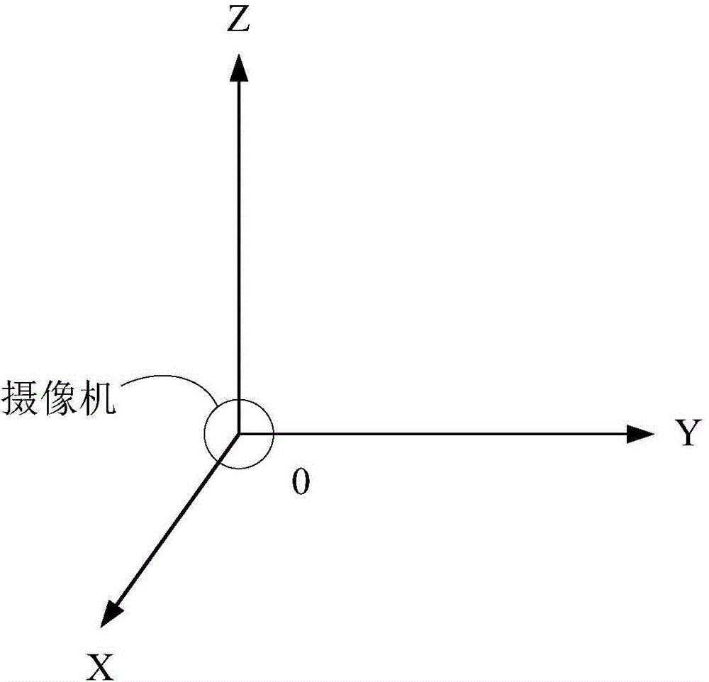
[0058] In view of the above problems, the present invention provides a camera displacement compensation scheme, which can perceive the camera position change caused by factors such as external environment vibration through a vector sensor, and feed back the change information to a control unit, such as MCU (Micro Control Unit, micro control unit) , so as to adjust the magnification of the movement, and control the stepping motor to adjust the angle of the camera for displacement compensation. At the same time, the camera can focus on the original monitored object after the position is shifted by refocusing.

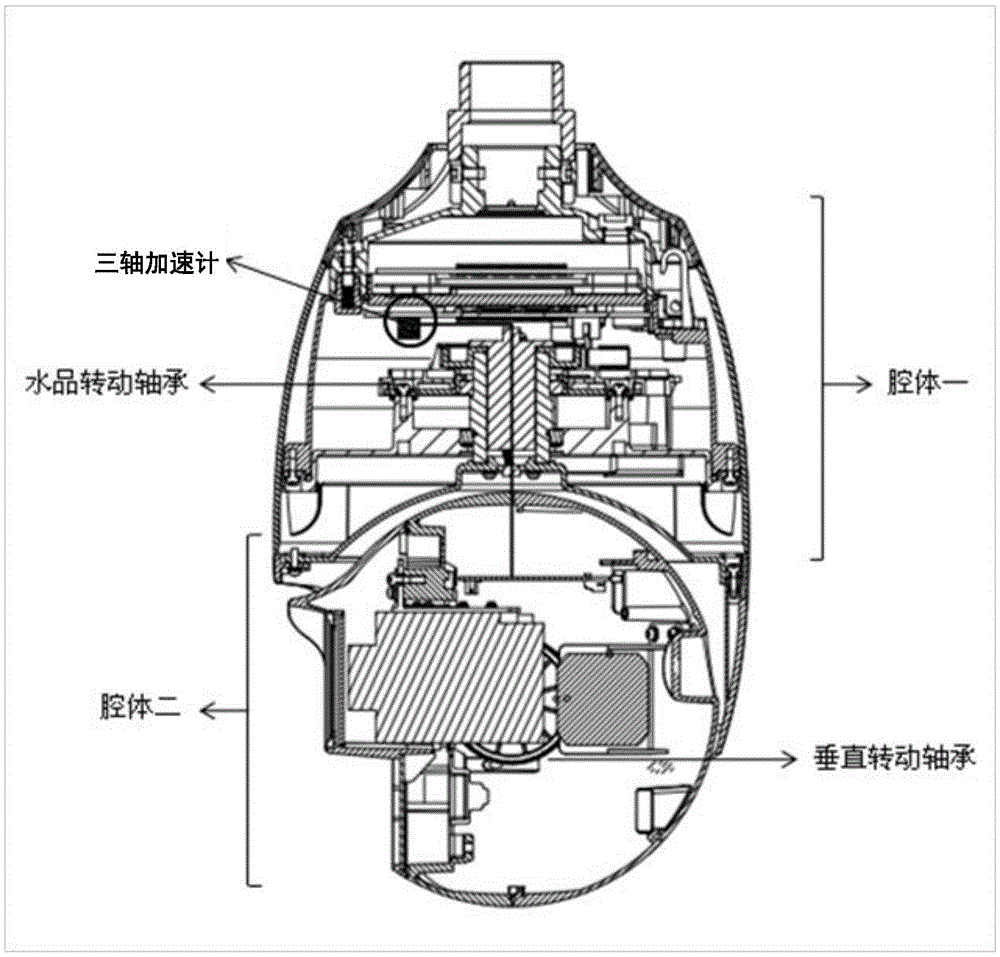
[0059] Since the deflection direction of the camera after being shaken is not fixed, in one embodiment of the present invention, a three-axis vector sensor may be selected as the vector sensor. Please refer to figure 1 , the vector sensor is a three-axis accelerometer. Taking a dome camera as an example, the vector sensor may be placed in a cavity of the dome camera. Of...


PUM


Abstract

The invention provides a camera displacement compensation method and device. The method comprises the following steps: establishing a space rectangular coordinate system, and computing the initial angle of a camera and a first object distance between the camera and a monitored object at an initial position; receiving the spatial position change information of the camera transmitted by a vector sensor when the position of the camera is changed; computing the second object distance and the second angle of the camera at a current position respectively according to the spatial position change information, the initial angle and the first object distance based on three coordinate axes of the space rectangular coordinate system; and driving a stepping motor to adjust the angle of the camera according to the initial angle and the second angle, and focusing according to the second object distance. Through adoption of the method and the device, anti-shock and anti-shake functions of the camera are realized.

Description

technical field [0001] The invention relates to the technical field of cameras, in particular to a camera displacement compensation method and device. Background technique [0002] With the continuous development of video surveillance technology, surveillance cameras have been widely used in the surveillance of various industries. Among them, the camera can be installed in a variety of ways, such as: wall, column, corner, pole, etc., and can even be directly hung on the cableway. If the camera is shaken, it will deviate from its original position, resulting in the inability to focus on the original object, and more seriously, the originally focused object will deviate from the camera's window range. [0003] To solve the above problems, the camera can use EIS (Electric Image Stabilizer, electronic image stabilizer) electronic anti-shake technology to analyze the image on the CCD (Charge-coupled Device, charge-coupled device), and then use the edge image to compensate. Howe...

Claims


Application Information

Patent Timeline
IPC IPC(8): H04N5/232H04N7/18G05D3/12
Inventor 徐燕飞李晗
Owner ZHEJIANG UNIVIEW TECH CO LTD
Why Eureka
Try Eureka