Battery system

A battery system and battery technology, applied in the field of battery systems, can solve problems such as accelerated battery aging, and achieve the effect of avoiding system failures

Active Publication Date: 2014-11-05
ROBERT BOSCH GMBH +1
View PDF3 Cites 0 Cited by
  • Summary
  • Abstract
  • Description
  • Claims
  • Application Information

AI Technical Summary

Problems solved by technology

If said capacity is exceeded, the aging of the accumulator can be strongly accelerated

Method used


Image

  • Battery system
  • Battery system
  • Battery system

Examples


Embodiment Construction

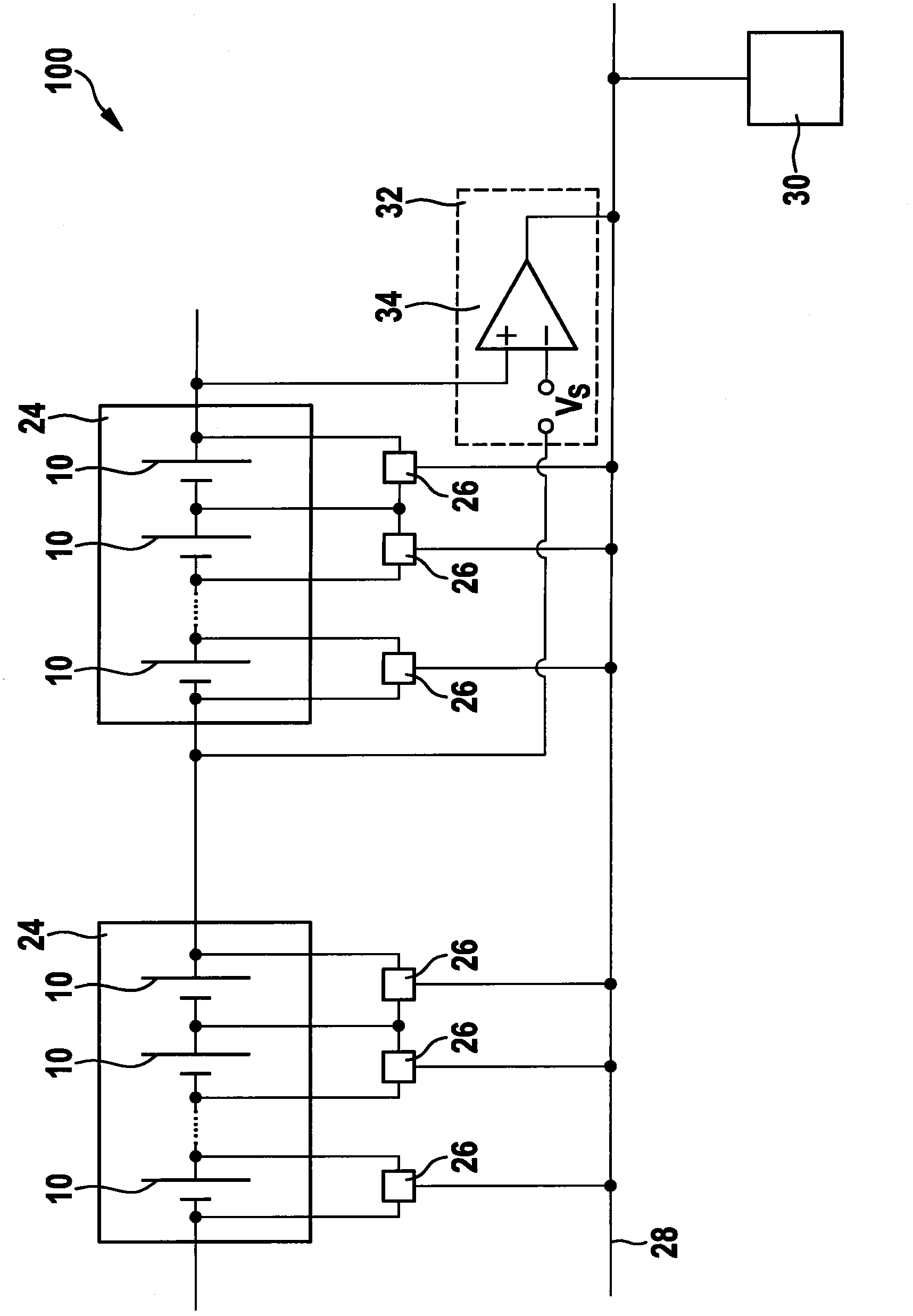
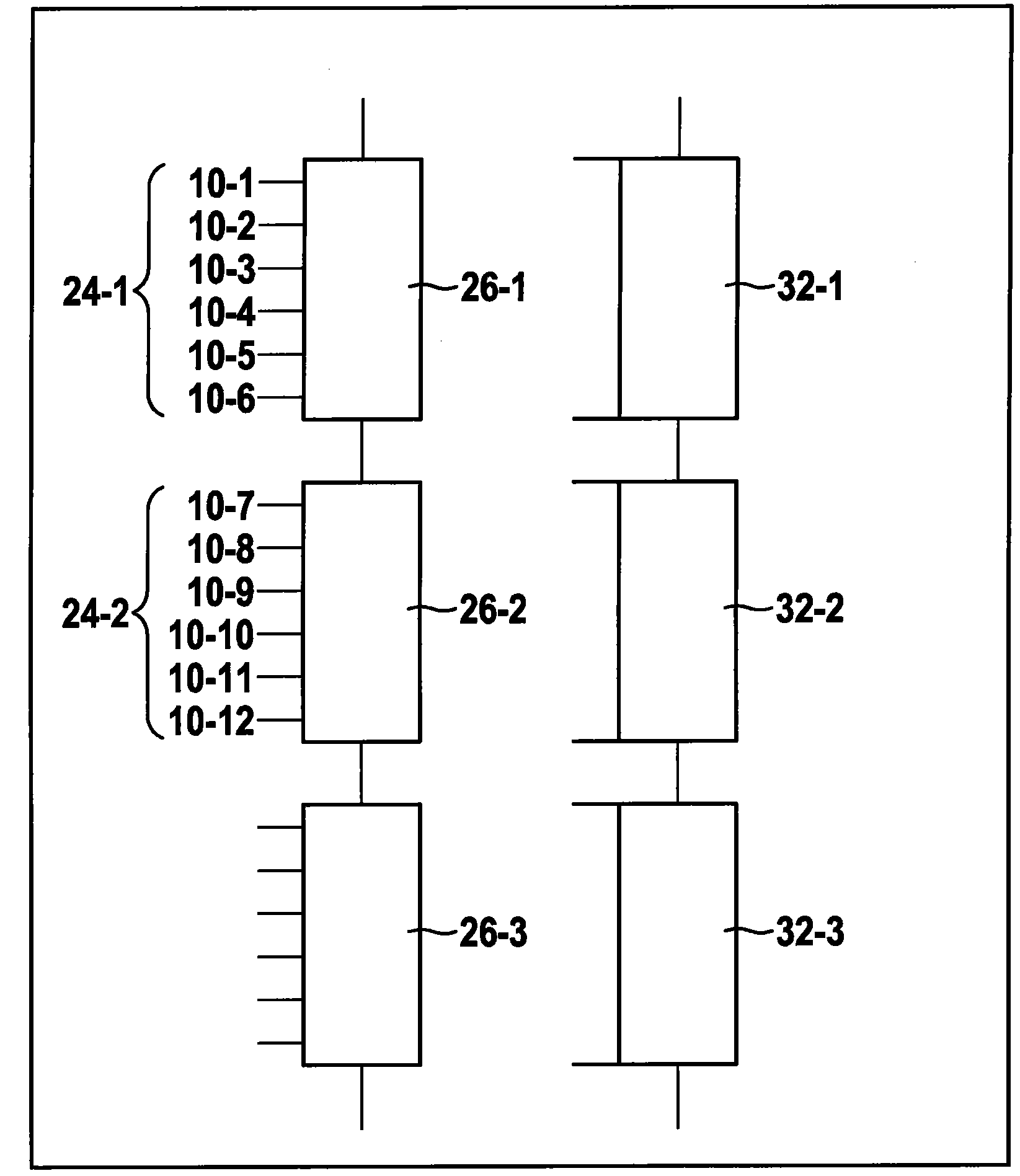
[0023] figure 2 Shown is a battery system 100 in which a large number of battery cells 10 are connected in series and combined into a large number of modules 24 . A module 24 includes a predetermined number of battery cells 10, typically between six and twelve. The acquisition device 26 respectively measures the voltage of each battery cell 10 and transmits the voltage value to a field bus 28 to which an evaluation unit 30 is connected. The evaluation unit 30 can control a high-voltage contactor to protect the battery system 100 . attached figure 2 The fieldbus systems 28 in the are networked via a bus-topology and use the CAN (Control Area Network)-protocol.

[0024] In addition, a large number of monitoring devices 32 are connected to the field bus 28 (see appendix figure 2 only one of the monitoring devices is displayed). The monitoring devices 32 each have a comparator 34 which compares the voltage on a module 24 with a predetermined voltage threshold value Vs.

...


PUM


Abstract

The invention relates to a battery system (100) having a plurality of battery cells (10) and a battery management unit. The battery management unit comprises a plurality of acquisition devices (26-1, 26-2) and a plurality of monitoring devices (32-1, 32-4, 36), wherein each of the acquisition devices (26-1, 26-2) is designed to acquire at least one operating parameter of the battery cells (10-1, 10-6; 10-7, 10-12) associated with same, and wherein each of the monitoring devices (32-2) is associated with a plurality of battery cells (10-4, 10-9), and each of the monitoring devices (32-2) is designed to monitor the operating parameter of the battery cells (10-4, 10-9) associated with same. The battery cells (10-4, 10-9), which are each associated with one of the monitoring devices (32-2), are associated with at least two acquisition devices (26-1, 26-2).

Description

technical field [0001] The invention relates to a battery system and to a motor vehicle with the battery system according to the invention. Background technique [0002] It has been shown that the increasing use of battery systems in the future, both in stationary applications (eg in wind power plants) and in vehicles (eg in hybrid and electric vehicles), has implications for the reliability of such battery systems made particularly high demands. [0003] The background to these high demands is that the failure of the battery can lead to the failure of the entire system. For example, a failure of the traction battery in an electric vehicle can lead to "squatting". Furthermore, failure of the battery can lead to safety-related problems. Batteries are used, for example, in wind power plants in order to protect the plant from impermissible states by adjusting the rotor blades in the event of strong winds. [0004] in the attached figure 1 Shown is a schematic diagram of a ...

Claims


Application Information

Patent Timeline
Patent Type & Authority Applications(China)
IPC IPC(8): H01M10/48H01M10/42G01R19/165G01R31/36B60L11/18
CPCH01M10/482B60L11/1853B60L11/1864Y02T10/7005G01R31/362H01M10/425Y02T10/7061G01R31/3658B60L58/18B60L58/21G01R31/396G01R31/3835Y02T10/70Y02E60/10H01M10/4257H01M2220/20
Inventor M·朗
Owner ROBERT BOSCH GMBH
Why Eureka
Try Eureka