Power supply system, and method for adjusting an output variable of the amplifier stage of a power supply system

A technology of power supply system and output variable, applied in amplifiers with semiconductor devices/discharge tubes, parts of amplifiers, amplifiers, etc., can solve problems such as shortening service life and damage to transistors

Active Publication Date: 2018-02-23
TRUMPF HUETTINGER GMBH CO KG
View PDF8 Cites 0 Cited by
  • Summary
  • Abstract
  • Description
  • Claims
  • Application Information

AI Technical Summary

Problems solved by technology

In particular, the transistor has the risk of being damaged in handling or significantly reducing its useful life

Method used


Image

  • Power supply system, and method for adjusting an output variable of the amplifier stage of a power supply system
  • Power supply system, and method for adjusting an output variable of the amplifier stage of a power supply system
  • Power supply system, and method for adjusting an output variable of the amplifier stage of a power supply system

Examples


Embodiment Construction

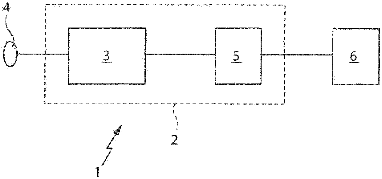
[0027] figure 1 A plasma system 1 comprising a power supply system 2 is shown. The power system 2 in turn comprises a power converter 3 which can be connected to a voltage supply network 4 . The power generated at the output of the power converter 3 is transferred through the impedance matching network 5 to the plasma chamber 6 where plasma is generated which can be used for plasma machining in the plasma chamber 6 . In particular, the workpiece can be etched or a layer of material can be applied to the substrate.

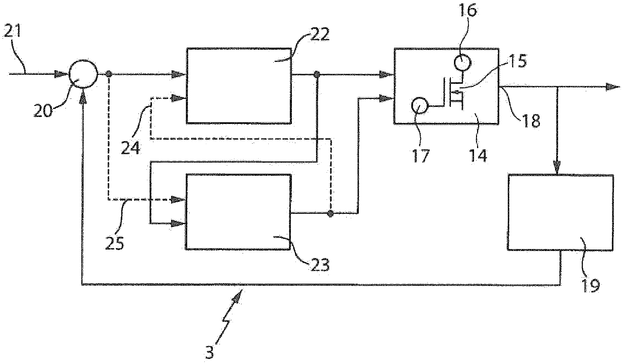
[0028] figure 2 show from figure 1 part of the power system 3. In particular, the power supply system 3 comprises an amplification stage 14 comprising at least one transistor 15 . Transistor 15 is connected to the supply voltage via power terminal 16 . The transistor is connected via a drive terminal 17 to a drive voltage, eg a gate voltage or a base voltage. At an output 18 of the amplifier stage 14 , the amplifier stage 14 generates an output signal, in p...


PUM


Abstract

A power supply system (2) comprises an amplifier stage (14) that includes at least one transistor (15), in particular an LDMOS transistor, which is connected to a supply voltage via a power connection(16); the control connection (17) of the transistor (15) is controlled by a control voltage; a first controller (22) is provided for adjusting the control voltage of the transistor (15), and a secondcontroller (23) is provided for adjusting the supply voltage; one of the controllers (22, 23) is designed to feed a state signal to the other controller (23, 22), and the other controller (23, 22) isdesigned to evaluate the state signal.

Description

technical field [0001] The invention relates to a power supply system comprising an amplification stage and also to a method for regulating the output variable of the amplification stage of the power supply system. Background technique [0002] Such devices and methods and similar prior art are known from the following documents, for example: US2008 / 0284510A1, US8,095,090B2, US2007 / 0145900A1, DE102013226511A1, US2014 / 0084700A1, US2009 / 0004981A1. [0003] Power supply systems, in particular systems that generate electrical power at a frequency ≧1 MHz, are used, for example, for laser excitation, in plasma coating systems, or also for induction applications. Such power systems include amplifiers that generate the power supplied to plasma coating equipment, induction applications or laser excitation. In theory, there are two concepts for controlling the power of the amplifier. In amplitude control, the output power of the amplifier is controlled by the amplitude of the input ...

Claims


Application Information

Patent Timeline
Patent Type & Authority Applications(China)
IPC IPC(8): H03F1/02H01J37/32H03F3/193H03F3/20
CPCH01J37/32174H03F3/193H03F3/20H03F1/0233H03F3/345
Inventor A·格雷德D·格吕纳C·博克A·佩娜维达尔M·沃尔德姆布罗克
Owner TRUMPF HUETTINGER GMBH CO KG
Why Eureka
Try Eureka