Wire clamp mounting structure and lead wire partitioning rod with the same

A technology for installing structures and spacers, which is applied in the direction of mechanical vibration attenuation devices, devices for maintaining the distance between parallel conductors, etc., can solve the problems of limited buffering and shock absorption capacity of the support frame, high production cost, and short service life of the support frame, etc., to achieve Reduce the structure complexity and production cost, ensure the service life, and the effect of low production cost

Inactive Publication Date: 2014-11-12
STATE GRID CORP OF CHINA +1
View PDF6 Cites 4 Cited by
  • Summary
  • Abstract
  • Description
  • Claims
  • Application Information

AI Technical Summary

Problems solved by technology

The problem with the existing wire spacers is that the support frame is a casting structure, which needs corresponding molds to make, and the production cost is high; in addition, the support frame is rigidly connected with the wire clamp, and when the split wire is shaken due to the force , the wire clips will exert a direct force on the supporting frame, the buffering and shock absorption capacity of the supporting frame is limited, and the service life of the supporting frame is short; what’s more, in order to realize the movable range of the split wire within a certain angle, the The wire clamp is hinged to the supporting frame, which makes the structure of the whole wire spacer bar complicated, further increasing the manufacturing cost of the wire spacer bar

Method used


Image

  • Wire clamp mounting structure and lead wire partitioning rod with the same
  • Wire clamp mounting structure and lead wire partitioning rod with the same
  • Wire clamp mounting structure and lead wire partitioning rod with the same

Examples


Embodiment Construction

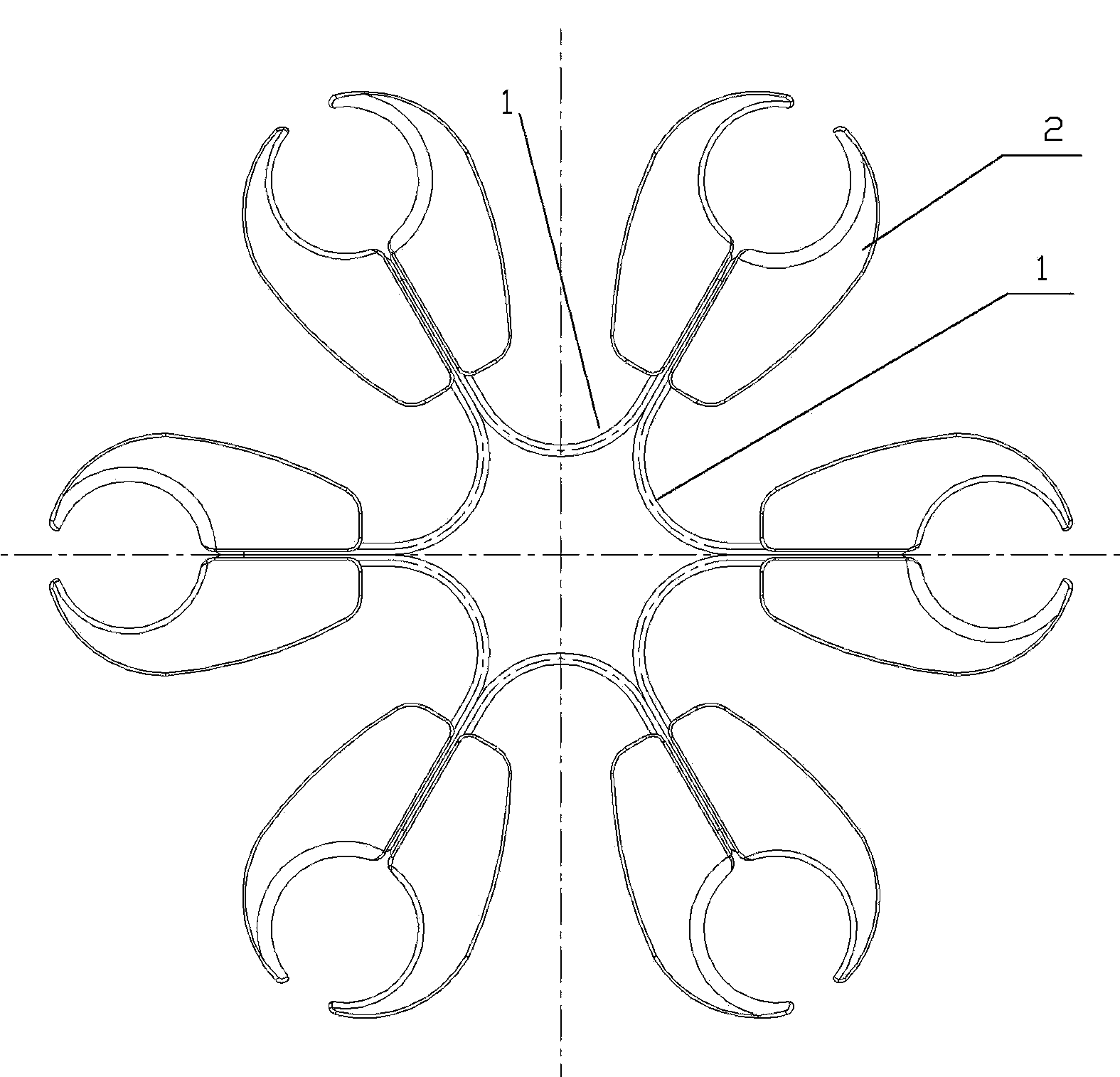
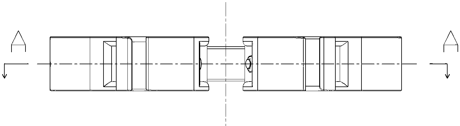
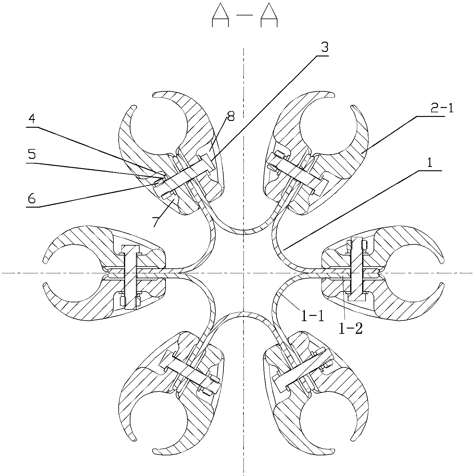
[0023] Examples of wire spacers are Figure 1~3 As shown: it includes a base body and six wire clips 2 evenly distributed on the base body around the circumference. Aluminum alloy bent plates, each U-shaped bent plate includes a bottom connecting plate 1-1 and two side plates 1-2 arranged at both ends of the bottom connecting plate, which can be elastically deformed opposite and opposite each other, and two adjacent U-shaped bent plates The two adjacent side panels of the board are set against each other. Each wire clamp is respectively fixed on two adjacent side plates corresponding to two adjacent U-shaped bent plates through a bolt connection structure, and the wire clamp includes two clamps clamped on both sides of the corresponding two adjacent side plates. Holder 2-1, the bolt connection structure includes connecting bolts 3 mounted on the two adjacent side plates and two clamping bodies and lock nuts 6 screwed on the connecting bolts, one of the clamping bodies A bolt...


PUM


Abstract

The invention relates to a wire clamp mounting structure and a lead wire partitioning rod with the same. The lead wire partitioning rod comprises a base body and at least three lead wire clamps which are evenly distributed on the base body in the periphery direction. The base body comprises at least three U-shaped bending plates which are evenly arranged in the periphery direction, and openings of the U-shaped bending plates are outward. The U-shaped bending plates are provided with bottom connecting plates and side plates. Two side plates are arranged at the two ends of each bottom connecting plate and can carry out elastic deforming oppositely and with the backs against each other. Each lead wire clamp is arranged to two adjacent side plates of two corresponding adjacent U-shaped bending plates. The lead wire partitioning rod is simple in structure and has buffering and shock weakening capacity.

Description

technical field [0001] The invention relates to a wire clip installation structure used in power transmission lines and a wire spacer using the installation structure. Background technique [0002] In long-distance, large-capacity EHV transmission lines, two, three, four or more split conductors are used for each phase conductor. In order to ensure that the distance between the split wire harnesses remains constant to meet the electrical performance, reduce the surface potential gradient, and in the case of a short circuit, the electromagnetic force generated between the wire harnesses will not cause mutual attraction and collision, or prevent the external environment (wind, Rain, ice, etc.) on the spacing between the split conductors, it is necessary to set spacer bars at intervals along the conveying direction of the conductors. [0003] Existing wire spacers such as the "six-split wire spacer for transmission lines" disclosed in Chinese patent document CN 201018242Y, the...

Claims


Application Information

Patent Timeline
Patent Type & Authority Applications(China)
IPC IPC(8): H02G7/12H02G7/14
Inventor 常林晶王品珍雷咸伦李俊辉王刚张爱芳
Owner STATE GRID CORP OF CHINA
Why Eureka
Try Eureka