
High-strength motor shaft

A motor shaft, high-strength technology, applied in the directions of shafts, shafts and bearings, mechanical equipment, etc., can solve the problems of inconvenient positioning and welding of rib plates, unreasonable structure of the motor shaft, and inconvenient installation and use, etc. The phenomenon, the structure is simple and reasonable, and the effect of ensuring the accuracy

Inactive Publication Date: 2014-11-19
池州扬帆微电机有限责任公司
View PDF9 Cites 5 Cited by
  • Summary
  • Abstract
  • Description
  • Claims
  • Application Information

AI Technical Summary

Problems solved by technology

[0003] The purpose of the present invention is to provide a high-strength motor shaft to solve the problem that the traditional motor shaft structure in the prior art is not reasonable enough, the installation and use are not convenient enough, the torsion resistance is poor, the parts are likely to slip, the rib plate positioning welding is inconvenient, and the welding Stress concentration and deformation are easy to occur at the place, the installation accuracy is not high, and the service life is low

Method used


Image

  • High-strength motor shaft

Examples


Embodiment Construction

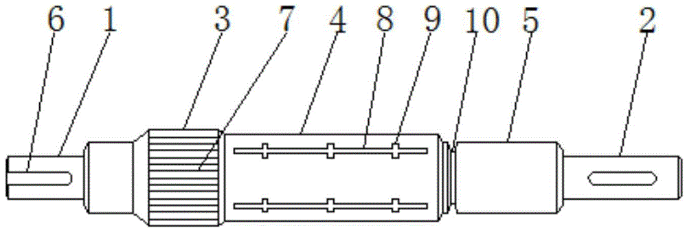
[0011] Such as figure 1 As shown, a high-strength motor shaft includes a front connecting rod 1 and a rear connecting rod 2, and a knurled rod 3, a first polished rod 4 and a second polished rod 5 are sequentially connected between the front connecting rod 1 and the rear connecting rod 2 , the outer circular surfaces of the front connecting rod 1 and the rear connecting rod 2 are provided with splines 6, the splines 6 on the front connecting rod 1 extend to the end face of the front connecting rod 1, and the outer circular surface of the knurled rod 3 is rolled There are straight knurls 7, and a plurality of axially arranged bar-shaped grooves 8 are equidistantly distributed on the outer surface of the first polished rod 4, and a plurality of cross-shaped reinforcing groove nodes 9 are distributed on the bar-shaped grooves 8.

[0012] An annular clamping groove 10 is provided between the first polished rod 4 and the second polished rod 5, and the motor shaft is made of high-st...


PUM


Abstract

The invention discloses a high-strength motor shaft. The high-strength motor shaft comprises a front connection rod and a rear connection rod, wherein a knurled rod, a first polished rod and a second polished rod are sequentially connected between the front connection rod and the rear connection rod; splines are arranged on the outer circle surfaces of the front connection rod and the rear connection rod; the splines on the front connection rod extend to the end side of the front connection rod; straight-line knurls are rolled on the outer circle surface of the knurled rod; a plurality of axial bar grooves are distributed at equal intervals in the outer circle surface of the first polished rod; a plurality of cross-shaped reinforcing groove nodes are distributed on the bar grooves. The high-strength motor shaft is simple and reasonable in structure, convenient to mount and use, small in possibility of skidding in the radial direction in the operation process, relatively good in torsion resistance, capable of conveniently locating and welding rib plates, good in stability and not easy for stress concentration and deformation; the precision of the motor shaft is effectively guaranteed; the service life of the motor shaft is prolonged; the normal operation of the motor is guaranteed.

Description

technical field [0001] The invention relates to the technical field of motors, in particular to a high-strength motor shaft. Background technique [0002] A motor is an electromagnetic device that converts or transmits electrical energy according to the law of electromagnetic induction. The motor shaft is one of the important components, and its performance directly affects the performance of the entire motor. The structure of the traditional motor shaft is unreasonable, the installation and use are not convenient enough, the torsion resistance is poor, and it is easy to cause parts to slip. Contents of the invention [0003] The purpose of the present invention is to provide a high-strength motor shaft to solve the problem that the traditional motor shaft structure in the prior art is not reasonable enough, the installation and use are not convenient enough, the torsion resistance is poor, the parts are likely to slip, the rib plate positioning welding is inconvenient, a...

Claims


Application Information

Patent Timeline
Patent Type & Authority Applications(China)
IPC IPC(8): F16C3/02
Inventor 方志根
Owner 池州扬帆微电机有限责任公司
Learn More