
Ranging method based on sound sensor and system thereof

A technology of a sound sensor and a ranging method, applied in the field of mobile communication, can solve the problems of large limitations, long time consumption, affecting generality, etc., and achieve the effect of small equipment limitations, strong method robustness, and good processing effect.

Active Publication Date: 2014-11-19
XIDIAN UNIV
View PDF5 Cites 8 Cited by
  • Summary
  • Abstract
  • Description
  • Claims
  • Application Information

AI Technical Summary

Problems solved by technology

But its shortcoming is: noise widely exists in all frequency bands, and it is still difficult to find an accurate Beep starting point due to the influence of noise after filtering the recorded audio, so for noisy indoor environments, the accuracy of distance measurement is limited will be greatly reduced, and therefore more limited
But its shortcomings are: 2-6KHZ Beep is audible to human ears, which affects the generality of the method; co-correlation technology is computationally intensive, time-consuming, and has poor robustness. Beep can be detected in various scenarios. The accuracy of the initial point is low, and it is greatly affected by the multipath effect, and the detection error is large
But its disadvantage is: this method needs to know the noise area in the audio accurately, so as to use the uniform distribution characteristics of the noise to distinguish, but the noise area in the audio is often difficult to know directly, because various delays will cause Beep arrival time and actual time have a large difference, so when there is a delay, the detection accuracy of this method is not high

Method used


Image

  • Ranging method based on sound sensor and system thereof
  • Ranging method based on sound sensor and system thereof
  • Ranging method based on sound sensor and system thereof

Examples


Embodiment Construction

[0031] The present invention will be further described below in conjunction with the accompanying drawings.

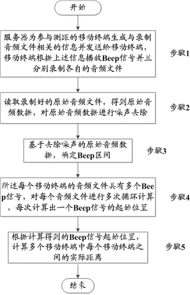
[0032] refer to figure 1 , shows a flow chart of an acoustic sensor-based ranging method 100 according to a preferred embodiment of the present invention. figure 1 Involving a ranging method based on a mobile terminal sound sensor and high-frequency sound, the ranging method 100 includes the following steps:

[0033] Preferably, in step 1, the ranging server generates the starting time of audio recording for each mobile terminal among the plurality of mobile terminals participating in the ranging, the starting time and playing time length of each mobile terminal playing Beep, and the recording The audio start time, play start time and play time length are sent to the corresponding mobile terminal, each mobile terminal starts to record the audio file at the recording audio start time with the microphone, and each mobile terminal plays the Start time and play time leng...


PUM


Abstract

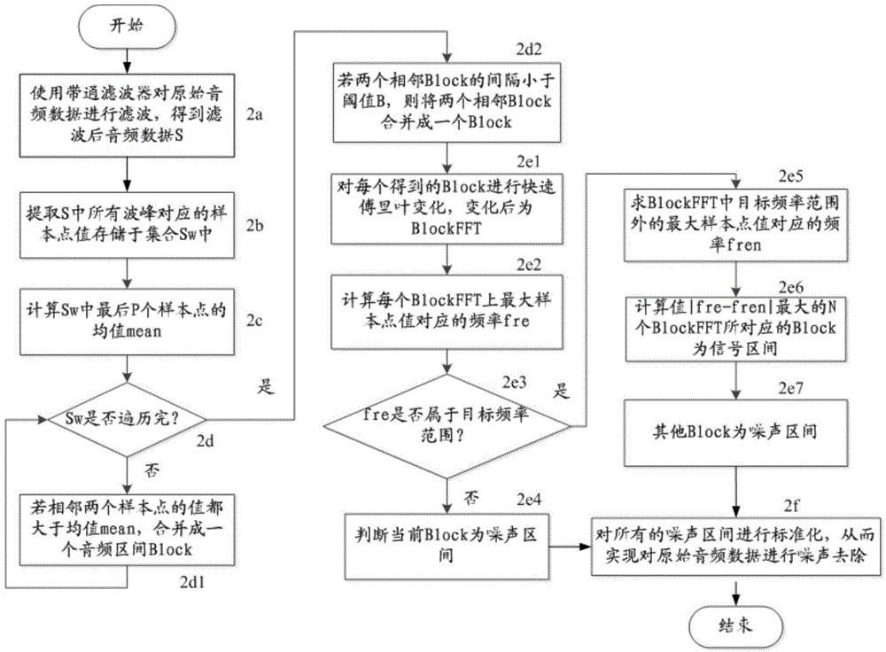
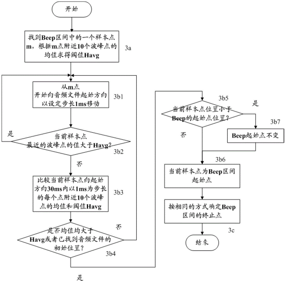
The invention relates to a ranging method based on a sound sensor and a system thereof. The method comprises the steps: (1) a ranging server generates the audio recording start time and the play start time and play time length of playing a Beep signal of each mobile terminal in a plurality of mobile terminals involved in ranging, each mobile terminal plays the Beep signal according to the play start time and play time length generated by the ranging server, and each mobile terminal in the plurality of mobile terminals records the respective audio file respectively, (2) the recorded original audio file is read, original audio data is obtained, and the noise removing is carried out on the original audio data, (3) based on the original audio data which is subjected to noise removing, a Beep interval is determined, (4) the audio file of each of the mobile terminals has a plurality of Beep signals, each audio file is subjected to multiple cycle calculation, and the start position of each Beep signal is calculated, (5) according to the calculated Beep signal start position, the actual distances between mobile terminals in the plurality of mobile terminals are calculated.

Description

technical field [0001] The present invention relates to the field of mobile communication technology, and in particular to terminal distance measurement technology, in particular to a distance measurement method and system based on sound sensors and high-frequency sounds in noisy environments, which can be applied to measure the distance between mobile terminals in noisy environments in the application. Background technique [0002] Ranging technology plays an important role in military affairs, production and daily life. With the widespread use of mobile terminals, accurate ranging using mobile terminals has become an increasingly common mobile terminal application and research direction. Ranging is mainly divided into short-distance ranging and long-distance ranging, and the ranging process is mainly divided into ranging after positioning and pure ranging. Ranging after positioning is mainly used for long-distance ranging, which refers to obtaining long-distance ranging d...

Claims


Application Information

Patent Timeline
IPC IPC(8): G01S11/14
CPCG01S11/14
Inventor 刘惠杜军朝孙继东郭煜昆潘馨张美清李曙聪张应昌华腾飞刘杰李国雄
Owner XIDIAN UNIV
Learn More