Puncture wire clamp

A technology for piercing wire clamps and bottom plates, which can be used in the direction of needle point/slotted plate contact parts used to penetrate insulating wires/cable core wires, multi-core cable end parts, etc., and can solve the problem that cannot meet the requirements of large-span main and branch lines Connection, unable to meet the main line and branch line connection, small distance and other problems

Inactive Publication Date: 2014-11-19
CHONGQING ZIYONG TECH
View PDF5 Cites 22 Cited by
  • Summary
  • Abstract
  • Description
  • Claims
  • Application Information

AI Technical Summary

Problems solved by technology

[0003] The puncture clamp with the above structure has a fixed size between the two clamping slots, which cannot meet the connection between the main line and the branch line at different interv

Method used


Image

  • Puncture wire clamp
  • Puncture wire clamp

Examples


Embodiment Construction

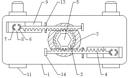
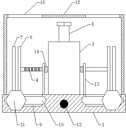
[0014] The present invention will be described in detail below in conjunction with accompanying drawing, as Figure 1-2 Shown: a puncture wire clamp, including a base plate 1, a gear rod 2 vertically arranged on the base plate, a sleeve 3 sleeved outside the gear rod, and a rack 4 that runs through the sleeve horizontally and meshes with the gear rod. The gear rod is rotatably connected with the bottom plate, and the top of the gear rod is provided with a torque nut 5, and the racks are two front and rear ones, and the end of the rack away from the gear rod is provided with a movable puncture blade 6, and a fixed puncture blade is provided facing the movable puncture blade 7. The fixed piercing blade is connected to the bottom plate through the slider 8, the bottom plate is provided with a chute 9 along the length direction of the rack, the slider is slidably connected to the chute, and the front and rear sides of the bottom plate are provided with The chute runs in the same d...


PUM


Abstract

The invention discloses a puncture wire clamp. According to the puncture wire clamp, wire clamping grooves are formed by fixed puncture blades and movable puncture blades, wherein the positions of the two fixed puncture blades are changed by adjusting the position of a sliding block in a sliding groove, then, the distance between the two wire clamping grooves is changed, and thus the puncture wire clamp can adapt to main wire and branch wire connection with different separation distances. Meanwhile, the adjustable range of the distance between the two wire clamping grooves is wide, and the puncture wire clamp can adapt to main wire and branch wire connection with large span.

Description

technical field [0001] The invention relates to the field of electric fittings, in particular to a piercing clip. Background technique [0002] Insulated cables are an important part of the power system. In order to realize the fast and safe connection of insulated cables, insulation piercing clamps are often used as quick connectors. The insulation puncture clamp in the prior art is mainly composed of an insulating upper cover, an insulating lower cover, an arc-shaped sealing rubber pad, and a piercing blade screw fastening assembly, wherein the screw fastening assembly includes a screw and a screw that penetrates the insulating upper cover and the insulating lower cover. The nut is sleeved on one end of the screw, and the nut is provided with a torque nut that breaks after clamping. The insulating upper cover and the insulating lower cover form two clamping grooves. The piercing blade is located in the clamping groove and wrapped in an arc-shaped sealing rubber pad. middl...

Claims


Application Information

Patent Timeline
IPC IPC(8): H01R4/24H01R11/11
Inventor 李勇冯庆云
Owner CHONGQING ZIYONG TECH
Why Eureka
Try Eureka