
A composite rotating water outlet assembly

A technology of rotating water outlet and components, which is applied in the direction of spraying device and spraying device with movable outlet, can solve the problems of inability to do both, difficult maintenance, high cost, and achieve perfect human comfort, perfect visual effect, and simple structure. Effect

Active Publication Date: 2016-12-28
XIAMEN SOLEX HIGH TECH IND CO LTD
View PDF6 Cites 0 Cited by
  • Summary
  • Abstract
  • Description
  • Claims
  • Application Information

AI Technical Summary

Problems solved by technology

[0003] Regardless of the above-mentioned rotation of the water surface or the rotation of the nozzle, it is often impossible to take care of both
If you want to directly combine the two, its mechanism will be very large and complex, with high cost and difficult maintenance.

Method used


Image

  • A composite rotating water outlet assembly
  • A composite rotating water outlet assembly
  • A composite rotating water outlet assembly

Examples


Embodiment 1

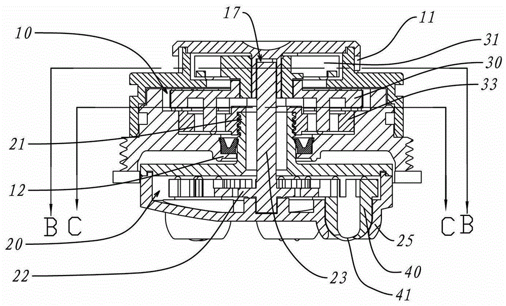
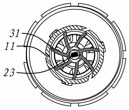
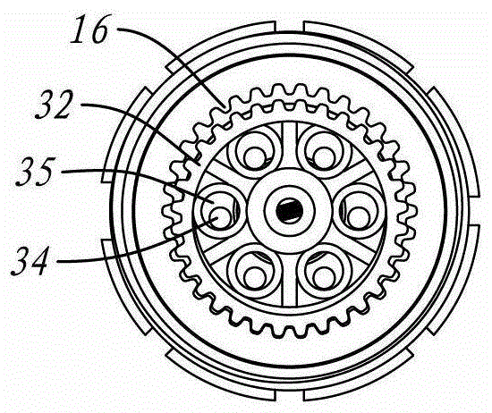
[0036] Such as Figure 1 to Figure 5 Shown is a schematic diagram of Embodiment 1 of the present invention. in Figure 1 to Figure 3 The overall mechanism is shown in the form of cross-section; Figure 4 is its exploded diagram; Figure 5 Details of its emergence from the water are shown.

[0037] In this embodiment, a composite rotating water outlet assembly includes two parts, one is a fixed fluid chamber 10 and the other is a dynamic fluid chamber 20 . As the name implies, the fluid chamber 10 itself is static, while the dynamic fluid chamber 20 is dynamic relative to the stationary fluid chamber 10 .

[0038] The constant fluid chamber 10 has a water inlet 11 and a water outlet 12, and has a power unit inside; The power unit has a power wheel 33 that outputs fixed-axis rotational power.

[0039] The dynamic fluid chamber 20 includes an input port 21 and several output ports 25; the input port 21 is sealed and rotatably fitted to the water outlet 12 of the constant fl...

Embodiment 2

[0050] Such as Image 6 , Figure 7 with Figure 8 Shown is a schematic diagram of Embodiment 2 of the present invention. Image 6 with Figure 7 The internal structure is shown in section,

[0051] The impeller mechanism of this embodiment is similar to the first embodiment. But the reduction mechanism is different, including: the first gear 14, the second gear 36 and the third gear 15; wherein the first gear 14 is coaxially fixed on the impeller 11; Coaxially arranged; the third gear 15 meshes between the first gear 14 and the second gear 36 ; the second gear 36 is coaxially fixed on the upper section of the power wheel 33 . The structure is all gear driven, with stable speed and low noise.

[0052] Such as Figure 8 As shown, the matching form of the water outlet 25 and the rotating body 40 in this embodiment is similar to that of the first embodiment, the difference is that the nozzle 41 is cylindrical, which provides a more concentrated water outlet effect.

Embodiment 3

[0054] Such as Figure 9 Shown is a schematic diagram of Embodiment 3 of the present invention.

[0055] The fixed fluid chamber 10 is located in the rotating part 8 of a shower, and the rotating part 8 has a switching hole, which can be matched with the input hole 9. When the rotating part 8 is rotated to a proper position, the switching hole can be aligned with the input hole 9, so that As for the water flow from the shower water channel 91 , it can enter the constant fluid chamber 10 to realize the effect of revolution + rotation.


PUM


Abstract

The invention discloses a composite rotary water output component which is characterized by comprising a fixed fluid cavity and a movable fluid cavity, wherein a power device is arranged inside the fixed fluid cavity, and the fixed fluid cavity further comprises a water inlet and a water outlet; the power device comprises a power wheel; the movable fluid cavity comprises an input port and a plurality of output ports; the input port is hermetically matched with the water outlet in a rotating manner, is coaxially fixed on the power wheel, and is communicated with the fixed fluid cavity; a driving wheel is arranged inside the movable fluid cavity, and the rotating shaft of the driving wheel passes through the input port and the water outlet to be fixed together with the fixed fluid cavity; auto-rotation bodies are arranged at the output ports, and are matched with the outer side of the driving wheel; and the autorotation bodies are provided with spray nozzles, and when rotating synchronously with the movable fluid cavity, the auto-rotation bodies are matched with the outer side of the fixed driving wheel to rotate automatically. According to the scheme, revolution and autorotation water output ways are combined, and a dynamic massaging effect is played. Moreover, in the scheme, the driving wheel is used as a linkage component for autorotation and revolution, and the structure is simple.

Description

technical field [0001] The invention relates to a component of sanitary equipment, in particular to a mechanism with the feature of rotating water outlet. Background technique [0002] The scheme of rotating the water has been formed in the existing sanitary equipment. Its characteristic is that multiple nozzles are set on the water outlet surface to discharge water at the same time, and then the driving device is used to drive the entire water outlet surface to rotate, so as to achieve the effect of multiple nozzles revolving in a large range to discharge water. Another type of rotating water outlet is the scheme of nozzle self-rotation, that is, the nozzle itself is driven by the driving device to rotate, forming a single stream of water that can rotate by itself. [0003] Regardless of the rotation of the above-mentioned water outlet surface or the rotation of the nozzle, it is often impossible to take both into account. If the two are to be combined directly, the mecha...

Claims


Application Information

Patent Timeline
Patent Type & Authority Patents(China)
IPC IPC(8): B05B3/04
CPCB05B3/0463
Inventor 曹勇斌陈健民杨玉蓉周华松
Owner XIAMEN SOLEX HIGH TECH IND CO LTD
Learn More