
Closed force transmission device and safety door lock using same

A safety door lock, closed technology, applied in locks with spring bolts, building locks, connecting components, etc., can solve the problems of easy switching, high manufacturing costs, and inability to be used, and achieve simple manufacturing processes and excellent durability. , the effect of high safety

Inactive Publication Date: 2014-11-26
金荣熙
View PDF4 Cites 1 Cited by
  • Summary
  • Abstract
  • Description
  • Claims
  • Application Information

AI Technical Summary

Problems solved by technology

Therefore, it is not easy to open and close the door not only for ordinary people, but also for children, disabled people, patients, etc. who are not free or have limited mobility.
[0005] Correspondingly, although there is a push-pull door lock that makes the door open and close easily by pushing and pulling the handle of the door, this existing door lock has the following disadvantages: the structure is complicated and the manufacturing cost is high due to the large number of parts, And additional door modification work is required when replacing the cylinder or tubular locks currently in use with push-pull locks
[0006] In addition, the above-mentioned existing door locks have low safety because the insertion depth of the deadbolt into the deadbolt slot cannot be increased beyond a certain depth in its structure, so a double locking device is often required
[0007] In addition, since the structure of the existing push-pull type door lock is different, the door handle to be used needs to be specially designed, so even a door handle with a desired design cannot be used if it is not suitable for the set door lock.

Method used


Image

  • Closed force transmission device and safety door lock using same
  • Closed force transmission device and safety door lock using same
  • Closed force transmission device and safety door lock using same

Examples


Embodiment Construction

[0047] Hereinafter, preferred embodiments of the present invention will be described in detail with reference to the accompanying drawings.

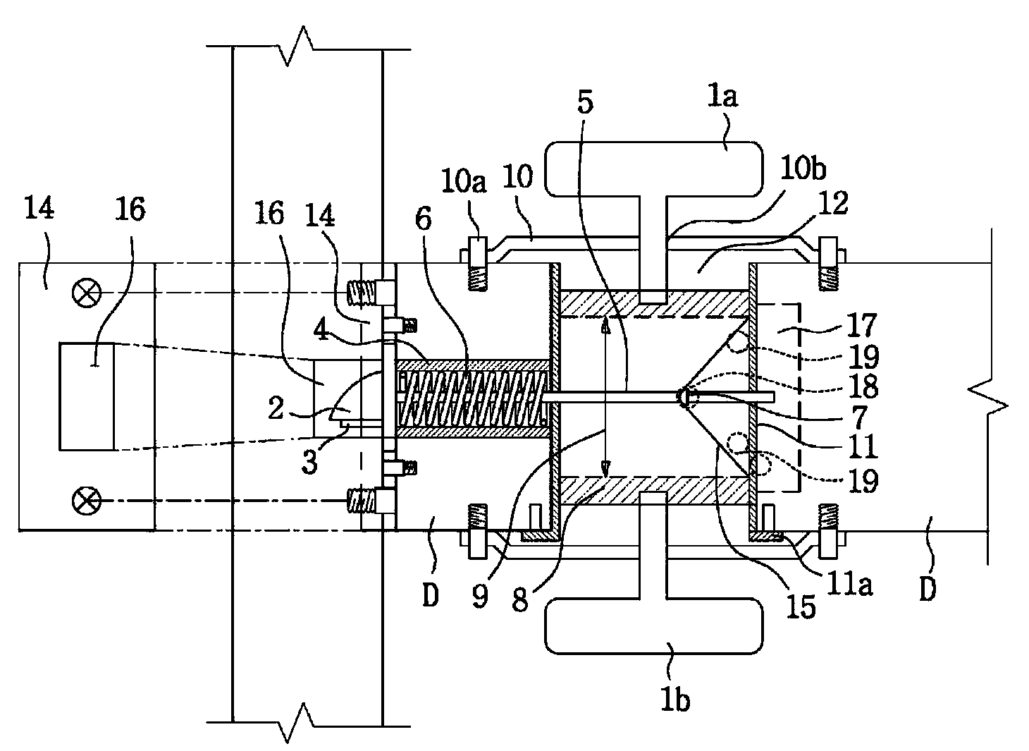
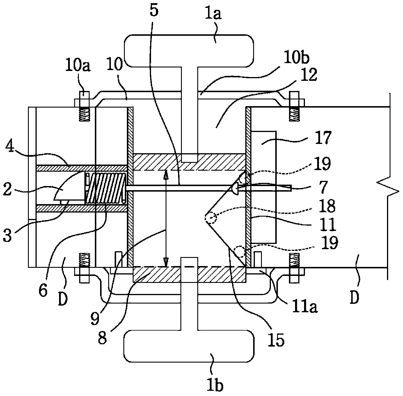
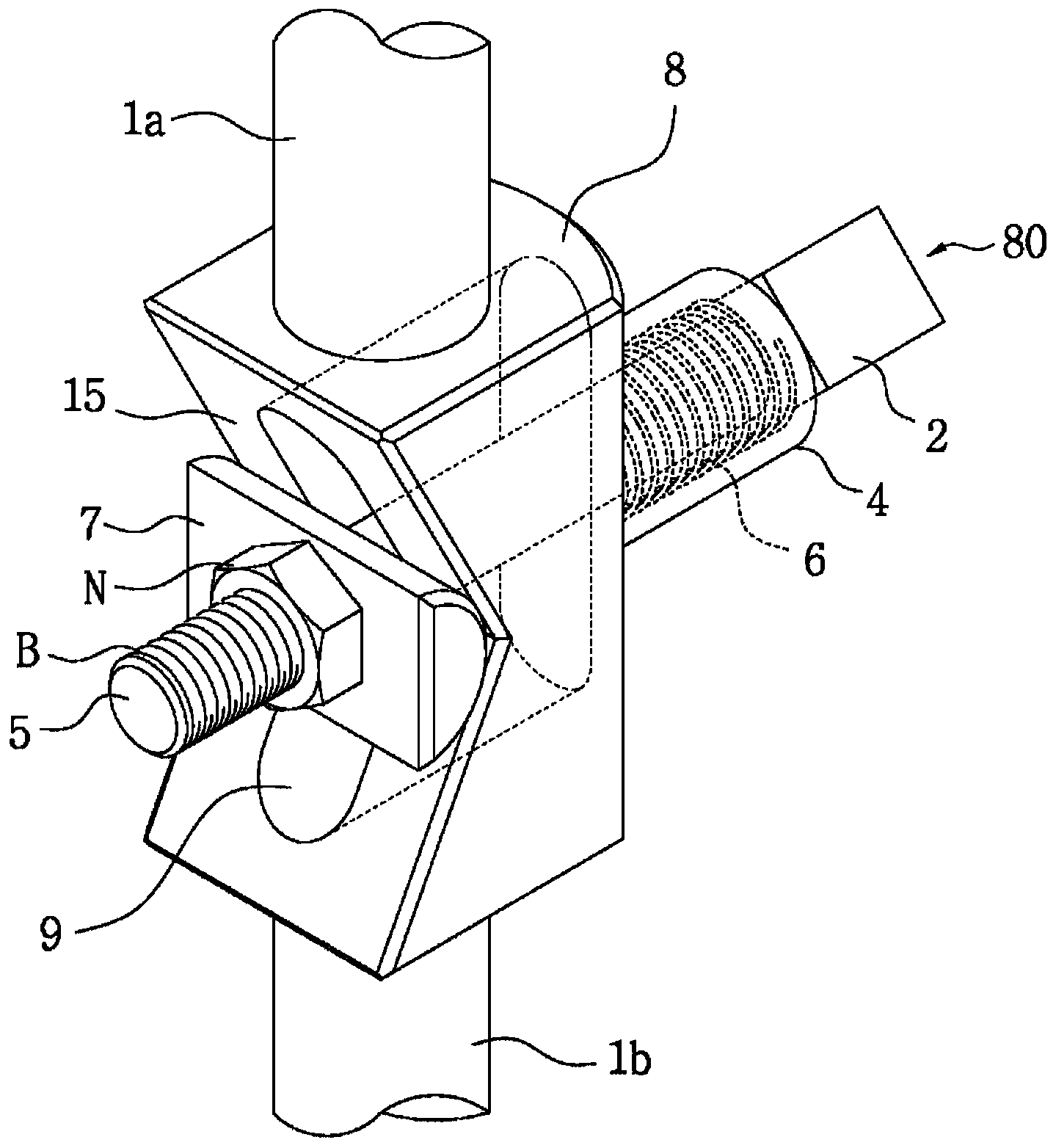
[0048] figure 1 is a schematic diagram showing a state where the safety door lock is closed according to the first embodiment of the present invention, figure 2 is showing figure 1 A schematic diagram of the state where the security door lock is opened, image 3 is a perspective view showing an assembled state of the force transmission device according to the first embodiment.

[0049] refer to Figure 1 to Figure 3 , The door lock includes a force transmission device and a handle 1a, 1b arranged on the door D. The force transmission device includes a body 8 and a bolt assembly 80 , and may also include a body shell 11 .

[0050] This door lock has a body shell 11, a body 8, handles 1a, 1b, and a bolt assembly 80, wherein the two sides of the body shell 11 are opened along the direction formed by the through holes 12 penetrating th...


PUM


Abstract

The present invention relates to a closed force transmission device in which an insertion depth of a latch bolt inserted into a latch bolt insertion groove can be adjusted to improve safety and components are simplified to allow for ease of assembly and to improve durability. The present invention also relates to a safety door lock using the device. The closed force transmission device of the present invention comprises: a cylindrical body housing of which both sides are opened to penetrate a door; a main body slidably arranged within the body housing such that the main body moves in a straight line direction by the force applied from an external source, the main body having at least one tilt surface and a main body movement space formed orthogonally to the straight movement direction in a portion corresponding to the tilt surface; a handle connected to the main body and protruded outwardly from both sides of the door; and a latch bolt assembly one end of which passes through the main body movement space and is coupled to the main body such that one end is vertically movable relatively to the movement direction of the main body and the other end of which is elastically supported at the body housing such that the other end is movable orthogonally to the movement direction of the main body in interlock with the straight line movement of the main body.

Description

technical field [0001] The present invention relates to a safety door lock, in particular to a closed force transmission device and a safety door lock using the same. The closed force transmission device and the safety door lock using the same make it safe because the insertion depth of the bolt inserted into the bolt slot can be adjusted. Performance is improved, and assembly productivity and durability are excellent due to simple constituent parts. Background technique [0002] A door lock is usually maintained in a locked state by inserting a deadbolt into a deadbolt slot formed on the door frame. At this time, the depth of the deadbolt inserted into the deadbolt slot is about 15mm, which is shallow. For a door lock with such a deadbolt insertion depth, a double locking device is required because the deadbolt can be forcibly removed from the deadbolt slot by using a screwdriver or the like to cause the door to be easily opened. [0003] Although this problem can be solve...

Claims


Application Information

Patent Timeline
Patent Type & Authority Applications(China)
IPC IPC(8): E05B55/14E05B59/04
CPCE05B63/06E05C1/14Y10T292/096E05B55/00E05B59/00E05C1/12
Inventor 金荣熙
Owner 金荣熙
Learn More