System and method for providing diagnostic fault information

A technology for diagnosing faults and information items, applied in general control systems, control/regulation systems, testing/monitoring control systems, etc., to achieve the effect of eliminating redundant information

Active Publication Date: 2014-11-26
SCANIA CV AB
View PDF8 Cites 6 Cited by
  • Summary
  • Abstract
  • Description
  • Claims
  • Application Information

AI Technical Summary

Problems solved by technology

[0007] Despite the many advantageous properties of the above solution, there is no effective solution for presenting appropriate information to the user of the diagnostic tool, such as a mechanic, when two or more faults occur simultaneously in a motor vehicle

Method used


Image

  • System and method for providing diagnostic fault information
  • System and method for providing diagnostic fault information
  • System and method for providing diagnostic fault information

Examples


Embodiment Construction

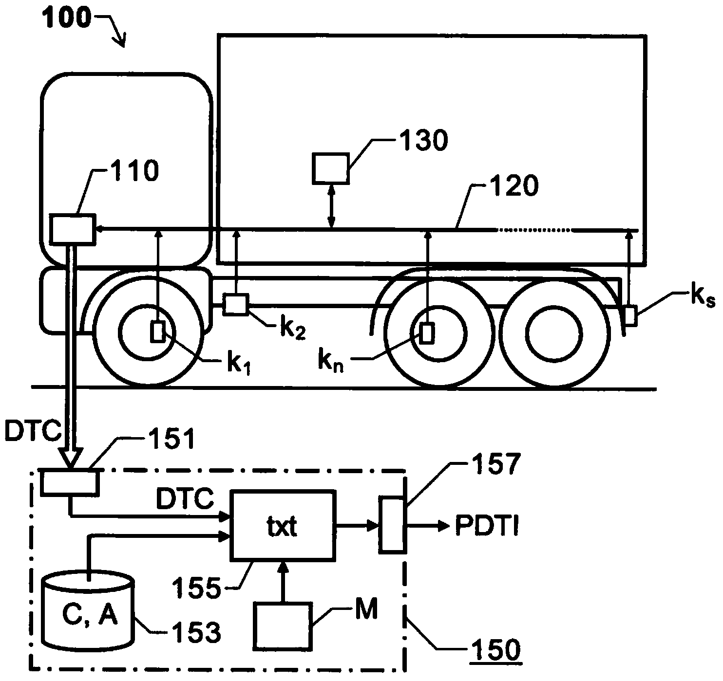
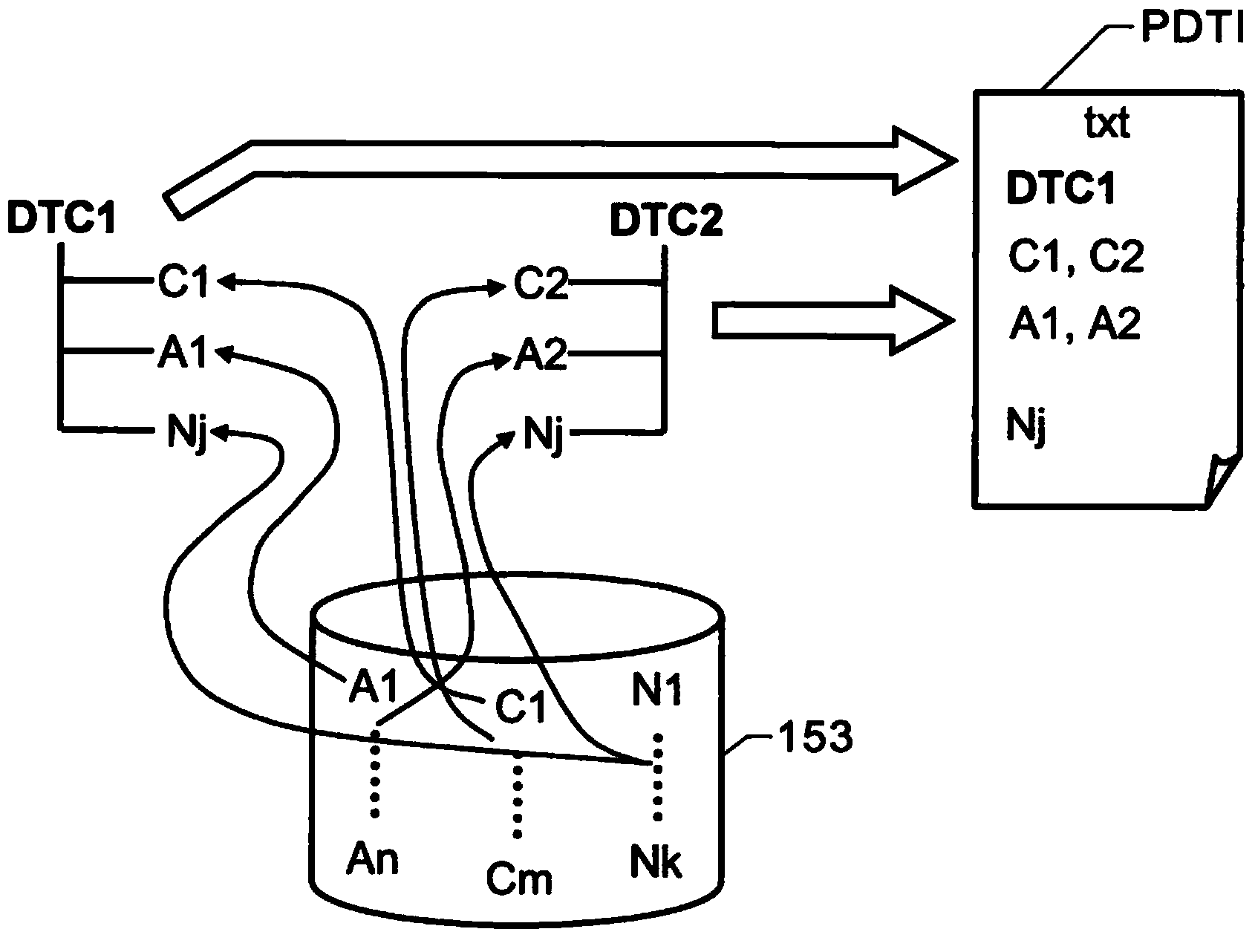
[0027] first reference figure 1 with figure 2 . figure 1 is a schematic diagram of a motor vehicle 100 connected to a system 150 to provide diagnostic trouble information PDTI in accordance with the present invention. figure 2 According to an embodiment of the present invention, it is shown graphically how to assemble and present diagnostic fault information PDTI.

[0028] Here the vehicle 100 comprises a number of components k 1 、k 2 ,...,k n ,...,k s . The first ECU 110 takes care of the first group of components k 1 and k 2 , the second ECU 130 takes care of the second set of components k n ,...,k s and part k 1 、k 2 ,...,k n ,...,k s communication between the ECU 110 and the ECU 130 across the communication bus 120. The first ECU 110 is considered to be also equipped with an interface for external data communication, for example for transmitting a fault code DTC to the proposed system 150 . Alternatively, system 150 may be integrated into vehicle 100 .

...


PUM


Abstract

A processing unit receives fault codes (DTC1, DTC2) from a vehicle and provides diagnostic fault information (PDTI) via an output interface. Each fault code received (DTC1, DTC2) is associated with an unique identity, and a database (153) contains at least one range of information items (A1 An; C1 Cm, N1, Nj) each pertaining to a certain fault code (DTC1, DTC2). The processing unit generates the diagnostic fault information (PDTI) dynamically on the basis of at least one fault code received (DTC1, DTC2) and at least one information item (C1, A1, Nj; C2, A2, Nj) thereto pertaining from the database (153).

Description

technical field [0001] In general terms, the present invention relates to identifying and correcting faults in motor vehicles. In particular, the invention relates to a system according to the preamble of claim 1 and a method according to the preamble of claim 12 . It also relates to a computer program according to claim 23 and a computer readable medium according to claim 24 . Background technique [0002] Today's motor vehicles are very complex technical systems supervised by automatic functions. For example, in heavy vehicles, such as trucks and buses, a unit or group of units is usually controlled by means of an electronic control unit (ECU), which is connected to the units via a communication bus. Thus, any faults in each component and unit of the vehicle can be detected via the corresponding ECUs that take care of them, and reported to central unit. [0003] DE 102007010978 A1 describes a solution for fault diagnosis, according to which Bayesian networks define cau...

Claims


Application Information

Patent Timeline
IPC IPC(8): G07C5/08G05B23/02G05B19/048
CPCG07C5/0808G05B23/0272G05B19/0428G05B23/0218
Inventor J·比泰斯M·尼贝里H·艾文达
Owner SCANIA CV AB
Why Eureka
Try Eureka