Supercharge Your Innovation With Domain-Expert AI Agents!

Cylinder compression head for assembly of brake master cylinder

A brake master cylinder and compression head technology, which is applied in the direction of manufacturing tools, metal processing, metal processing equipment, etc., can solve problems such as difficulty in guaranteeing, high friction between the end cover and the compression head, and difficulty in rotating the end cover. The effect of improving efficiency and reducing the difficulty of matching installation

Inactive Publication Date: 2016-08-24
浙江奔腾智能制动系统有限公司
View PDF6 Cites 0 Cited by
  • Summary
  • Abstract
  • Description
  • Claims
  • Application Information

AI Technical Summary

Problems solved by technology

The plunger part of the brake master cylinder is mainly equipped with a compression spring for plunger reset, a plunger and an end cover for fixing the compression spring and plunger in the plunger hole, wherein the upper part of the end cover is hexagonal column-shaped, There is a circular groove in the center of the upper end surface of the end cover, and an external thread that is matched with the brake master cylinder body is provided at the lower part of the end cover. During the assembly process, the brake master cylinder body is fixed first, and then the shaft end sleeve Press the compression spring, plunger and end cap that have been placed in the plunger hole of the brake master cylinder in advance into the plunger hole for the cylinder with a compression head, and then screw the end cap into the plunger hole with a wrench. In the process of pressing the end cover down with the cylinder, the pressing head is placed in the circular groove on the upper end surface of the end cover. In order to prevent the cylinder from stretching out and crushing the end cover or the pump body, it is usually necessary to press the cylinder while pressing it. Turn the end cap so that the end cap is screwed into the plunger hole in time, and then tighten the end cap with a dead wrench. However, due to the high friction between the end cap and the compression head, it is difficult to turn the end cap, so you must use a dead wrench, etc. tool, making it difficult to turn the end cap in time as it enters the plunger hole

Method used


Image

  • Cylinder compression head for assembly of brake master cylinder
  • Cylinder compression head for assembly of brake master cylinder
  • Cylinder compression head for assembly of brake master cylinder

Examples


Embodiment Construction

[0014] In order to make the technical means, creative features, goals and effects achieved by the present invention easy to understand, the present invention will be further elaborated below.

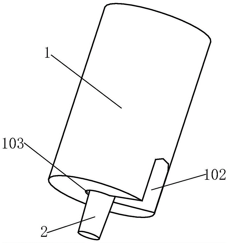
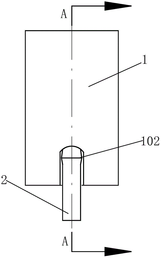
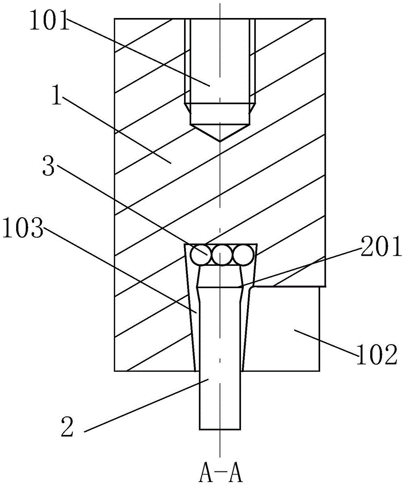
[0015] Such as Figure 1 to Figure 3 As shown, a cylinder compression head for assembly of a brake master cylinder includes a compression head main body 1, the compression head main body 1 is cylindrical, and a threaded hole 101 is provided in the center of the upper end surface of the compression head main body 1. When the compression head is fixed on the shaft end of the compression cylinder through the threaded hole 101, the center of the lower end surface of the compression head main body 1 is provided with an inverted tapered hole 103, and the bottom of the compression head main body 1 is provided with a flaring groove 102. The diameter of the inverted tapered hole 103 gradually increases from bottom to top, the inverted tapered hole 103 communicates with the flaring groove 102, an...


PUM


Abstract

The invention relates to an air cylinder press head for assembling a brake master cylinder. The press head comprises a press head body, wherein a threaded hole is formed in the center of the upper end surface of the press head body; an inverted tapered hole is formed in the center of the lower end surface of the press head body; a flared groove is formed in the lower part of the press head body and communicated with the inverted tapered hole; rolling bodies are distributed on the upper bottom surface of the inverted tapered hole; a press column penetrates through the inverted tapered hole; one part, which is located in the inverted tapered hole, of the press column is provided with a large-diameter area, and the diameter of the large-diameter area of the press column is larger than that of the opening of the inverted tapered hole. According to the press head, the manner that the press column can rotate on the rolling bodies arranged in the press head body is adopted, so that the moment required to be exerted for rotation of the press column is greatly reduced, when a shaft of an air cylinder presses an end cover towards a plunger hole, the end cover which is pressed against the lower end of the press column can be rotated timely by hand to be matched with an inner thread at one end of the plunger hole timely, the mounting efficiency of the end cover is greatly improved, and the matched mounting difficulty of the end cover is greatly reduced.

Description

technical field [0001] The invention relates to an assembly device for auto parts, in particular to a cylinder pressing head for assembly of a brake master cylinder. Background technique [0002] The brake master cylinder is a device in the automobile braking system that converts the mechanical energy of the driver's stepping on the brake into hydraulic energy. After the driver steps on the brake pedal, the pressure of the hydraulic oil in the brake master cylinder increases, and then the hydraulic oil is released It is transmitted to each brake cylinder to push the piston to move, and finally achieve the purpose of braking with friction. The plunger part of the brake master cylinder is mainly equipped with a compression spring for plunger reset, a plunger and an end cover for fixing the compression spring and plunger in the plunger hole, wherein the upper part of the end cover is hexagonal column-shaped, There is a circular groove in the center of the upper end surface of ...

Claims


Application Information

Patent Timeline
Patent Type & Authority Patents(China)
IPC IPC(8): B23P19/027
CPCB23P19/027
Inventor 夏坤财
Owner 浙江奔腾智能制动系统有限公司
Features
  • R&D
  • Intellectual Property
  • Life Sciences
  • Materials
  • Tech Scout
  • Unparalleled Data Quality
  • Higher Quality Content
  • 60% Fewer Hallucinations
Learn More