Mechanical arm

一种机械手臂、臂部的技术,应用在机械人领域,能够解决不利使用机械手臂、成本高、机械手臂制作成本高等问题,达到减少机械手臂需求的效果

Active Publication Date: 2014-12-03
HIWIN TECH
View PDF7 Cites 8 Cited by
  • Summary
  • Abstract
  • Description
  • Claims
  • Application Information

AI Technical Summary

Problems solved by technology

In robotics technology, especially robotic arms, have long been used in many automated factories, such as Japanese Patent Application Laid-Open No. 11-77566, which is a robotic arm used in liquid crystal panel factories to transport glass substrates. The end of the robotic arm can make Movements such as lifting, swinging, and turning left and right are used to easily pick up glass substrates. However, it is an indisputable fact that many servo motors are required to produce complex movements, resulting in high manufacturing costs for the robotic arm. This is not conducive to the large-scale use of robotic arms in factories.
Moreover, in some situations that only need to move and swing, such as loading and unloading operations on processing machines, using the aforementioned robotic arm is quite uneconomical for the factory, and there will be a problem of high cost
[0003] In order to solve the problem of high cost caused by the use of known robotic arms in the aforementioned simple operation situation, it is necessary to improve the current robotic arm by reducing the design direction of the servo motor, so as to meet the needs of some robotic arms that only need to move and swing

Method used


Image

  • Mechanical arm
  • Mechanical arm
  • Mechanical arm

Examples


Embodiment Construction

[0016] The technical contents and features of the present invention will be described in detail below by referring to the enumerated embodiments in conjunction with the accompanying drawings.

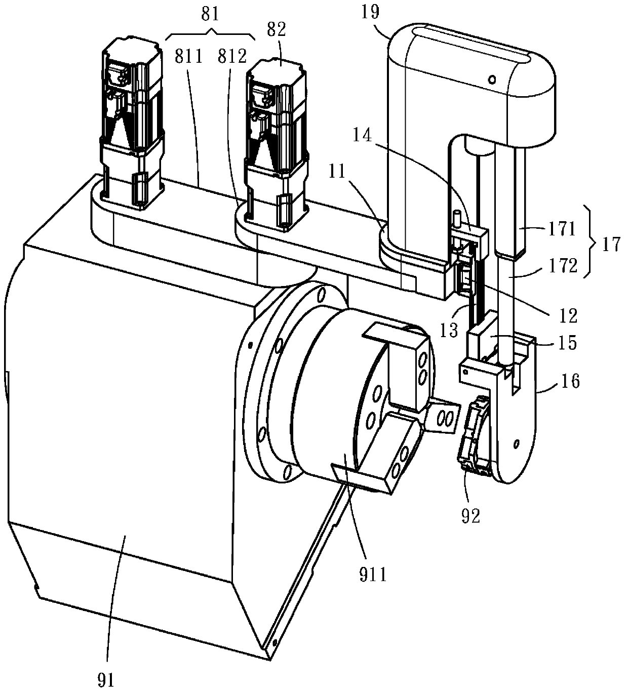
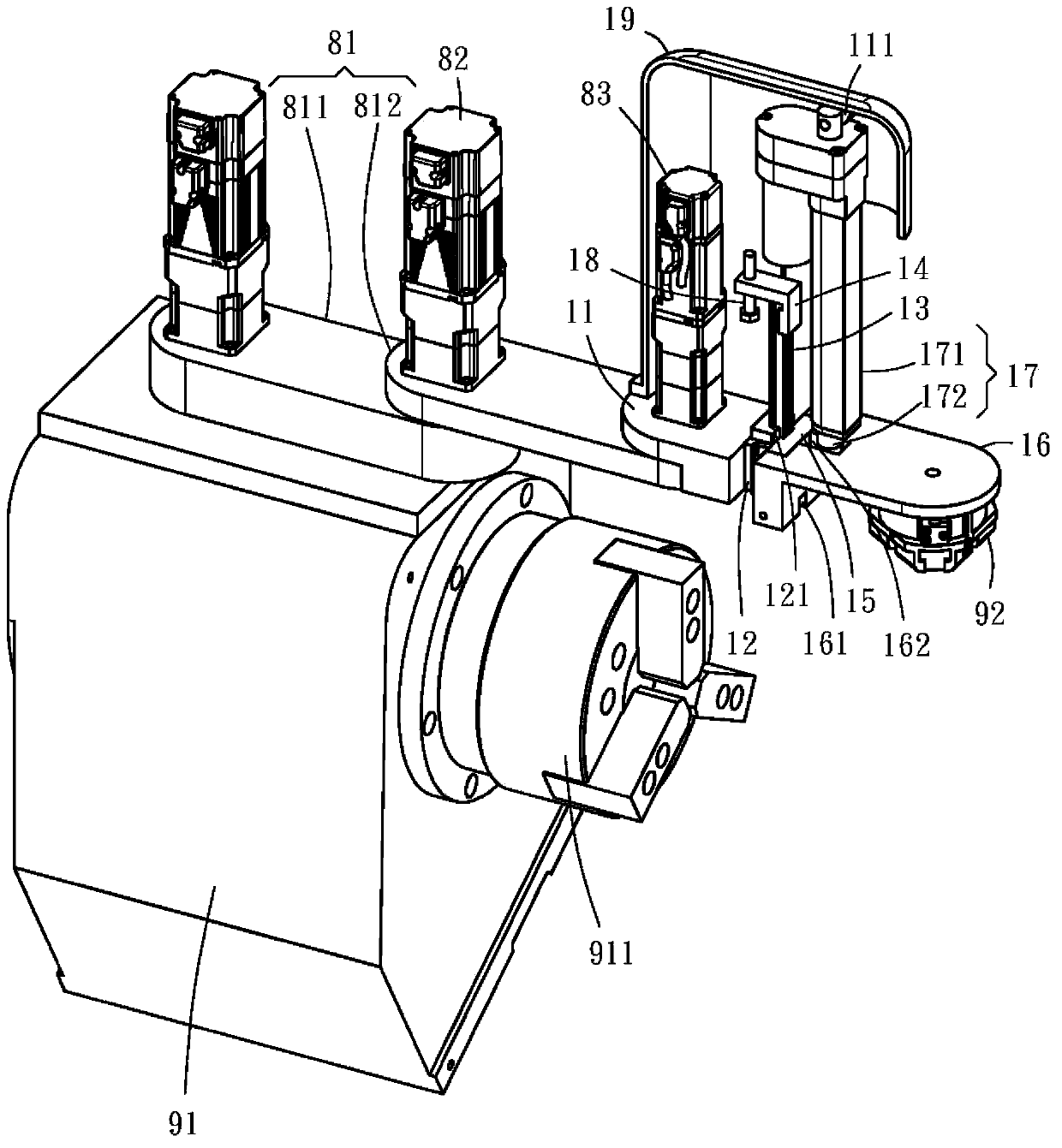
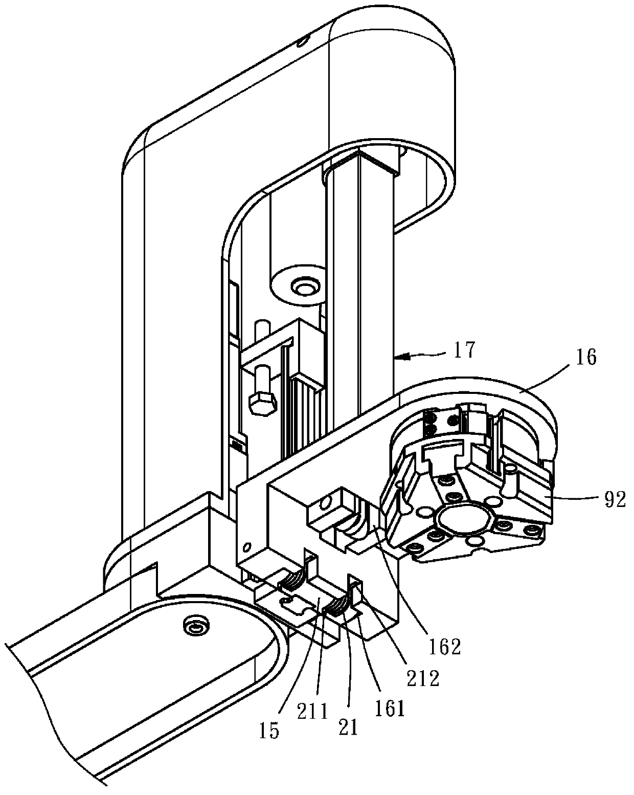
[0017] Please see first Figure 1 ~ Figure 3 , The mechanical arm provided by an embodiment of the present invention includes an arm 11 , a fixing part 12 , a sliding part 13 , a stopper 14 , a connecting part 15 , a wrist 16 and a driving device 17 .

[0018] Explain first here, in order to make the operation of the present invention appear more clearly, take the present invention is arranged on a moving arm 81 as an example, and this moving arm 81 has a first segment 811 and a second segment that are pivotally connected to each other 812 , wherein the first section 811 is pivotally connected to a processing machine 91 and can swing relative to the processing machine 91 . It should also be noted that the present invention is not limited to be installed on the moving arm 81 , and the p...


PUM


Abstract

The invention relates to a mechanical arm, which comprises an arm having a first pivot part, a fixing piece fixedly connected with one end of the arm, a sliding piece movably arranged on the fixing piece, a stopping piece fixedly connected with the sliding piece and used for limiting the stroke of the sliding piece, a connecting piece fixedly connected with the sliding piece, a wrist part having a second pivot part pivoted to the connecting piece, and a third pivot part, and a driving device having a body and an extending section, wherein the body is pivoted to the first pivot part, and the extending section is pivoted to the third pivot part of the wrist part. The fixing piece, the sliding piece, the stopping piece, the connecting piece and the wrist part are matched with the driving device to achieve the dual operation effect of movement and swinging, so the production cost is reduced.

Description

technical field [0001] The present invention is related to a robot, in particular to a structure of a mechanical arm. Background technique [0002] With the advancement of robot technology, unmanned chemical factories are no longer a distant dream. In robotics technology, especially robotic arms, have long been used in many automated factories, such as Japanese Patent Application Laid-Open No. 11-77566, which is a robotic arm used in liquid crystal panel factories to transport glass substrates. The end of the robotic arm can make Movements such as lifting, swinging, and turning left and right are used to easily pick up glass substrates. However, it is an indisputable fact that many servo motors are required to produce complex movements, resulting in high manufacturing costs for the robotic arm. This is not conducive to the large-scale use of robotic arms in factories. . Moreover, in some situations that only need to move and swing, such as loading and unloading operations ...

Claims


Application Information

Patent Timeline
Patent Type & Authority Applications(China)
IPC IPC(8): B25J11/00B23Q7/04
CPCB23Q1/4833B23Q1/5475B23Q1/5493B23Q7/04B23Q2707/003B25J9/044Y10T74/20335Y10S901/29B23Q1/5431B23B31/39Y10T483/171B25J17/02B25J17/025
Inventor 谢武灯
Owner HIWIN TECH
Why Eureka
Try Eureka